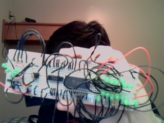
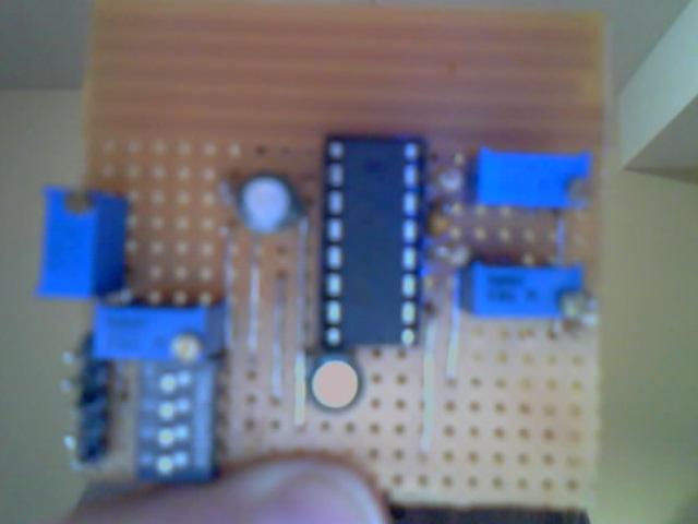
Here's a cool LED circuit controlled by a 555 timer (NE555), BCD counter (CD4510), and a 4:16 positive output decoder (CD4514). The circuit shown drives 17 LEDs. It works for multiples of 10, but I couldn't fit anymore LEDs on the bread board. The LEDs are divided into two sets of 10. Each set is connected in parallel. A 555 timer generates a clock, that increments a BCD counter. The counter outputs to a decoder to select a single LED of the set. The LED sets are positioned such that it looks like two lights travel are in a loop.
Improvements can be made my replacing the BCD counter with a binary counter (4516). doing so would allow for a set of 16 LEDs. The 555 timer could also be made tunable with a POT, instead of a resistor. The decoder could be replaced with an inverted logic decoder (4515), which would turn the selected input "off" and leave the remaining LEDs in the set "ON", or the decoder could output to NPN transistors. The transistors would invert the logical output of the decoder, turning the 4514 into a 4515. Transistors also provide more current than 4000 series ICs can source. Adding them lets you add add more LEDs.
I'm sorry my breadboard blocked out my face, but all I have is a webcam! The circuit is elementary, fun, inexpensive, and requires no programming. Don't mind the four LEDs and wires at the leftmost side of the board, they are from a another project. And sorry for my crazy wiring.
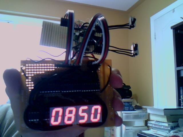
The chess clock, if you can make is out, is a circuit that switches between to different clocks whenever the top toggle switch is toggled. When the switch is high, clock 1 is displayed and decremented. When the switch is low, clock 2 is displayed and decremented. The second switch pauses and resets the clocks.
A PIC16F716 controls the clocks and performs all the processing. The display uses four 4511 latched BCD to seven segment display converters. It it possible to optimize the design by making a microcontrolled display, however, my display module is simple, and easy to interface with. For this use, the PIC16F716is overkill; but I needed a microcontoller with a timer module. Any microcontroller can be subsitituted. In the future, I plan to streamline the design, and make more polished and smaller.
Currently the time is pre-programmed to ten minutes. If more buttons can be added, it the software can be modified to allow for programmable timing, and different timing modes.
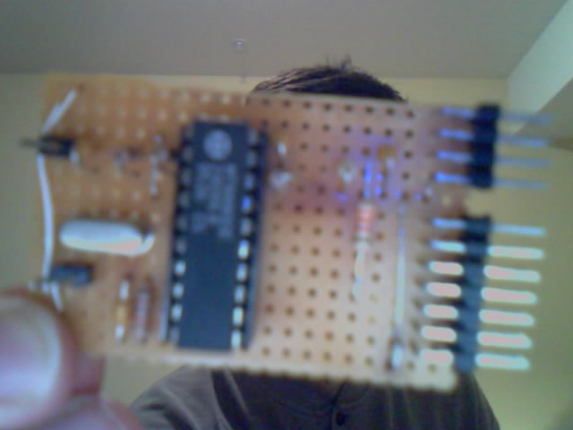
The MT8880 is the key component for the DTMF encoder/decoder. The IC is controlled my a microcontroller that interfaces with the digital lines of the MT8880. The analog RX and TX connects into a hybrid circuit that connects to the telephone line. What's not included is a ring detector. The circuit built lacks any surge supression. The ring signal sent on a telephone line can reach 90 Vrms, so be carefull. Lastly, the hybrid is not FFC certified DAAs can be bought to connect equipment to the telco service.
The telephone line consists of two wires, the tip and ring, which are charged at -48V and 0V respectively. The negative voltage is applied to prevent corrosion of the underground cables. First, the incomming hybrid circuit input connects to the telephone line through a full-wave rectifier circuit. This ensure the correct polarity of the tip and ring. At the output of the hybrid, a ~9V to ~15V zener diode should be placed to limit the voltage. For North America, the AC signal needs to have a 600 Ohm termination. Note, that this does not apply to the DC termination. Thus, the AC signal termination is achieved with a series combination of a 600 Ohm resistor and a 22 uF capacitor to ground. At this node, the TX signal can be fed from an open collector amplifier, and the input signal can be received from by an amplifier. My circuit uses an potiometer to control the gain on the input side. The MT8880 will output at the appropiate level.
The digital side requires four pins for the bi-directional data bus. There is one pin for R/W, IQR (interrupt request), chip select, Rs0 and phi2. Phi2 is for the MT8880 data bus clock. Some history reveals that the MT8880 was designed by Mitel (in CANADA!), to work with a Motorola bus. In fact, the data sheet shows how it can be memory mapped to a 6802. The motorola bustypically runs at 2 to 4 MHz, while low cost embedded uC, have peripherial speeds that are much slower. The solution was to tie phi2 high, and toggle the chipselect to act as a clock. Lastly R0 is important because it selects the MT8880's register. '0' to Rs0 selects the data register, where TX'd/RX'd data goes, while '1' selects the control register, where you can specify how the DTMF generator should work, i.e. output, stop, enable interrupt, etc.
One option is to use the telephone line voltage (now clamped to the zener voltage) to power the circuit, provided it does not drain more than 20 mA (which my circuit does). So it would great if the circuit had some ring detection, and some could power itself from the telephone line. The MT8880 uses 11 mA (max), and the uC adds another <10 mA (depending on speed). Which means that the hybrid circuit drains too much current. If the opamps where re-placed by transistors and if the uC operated slower than the circuit could become selfcontained.
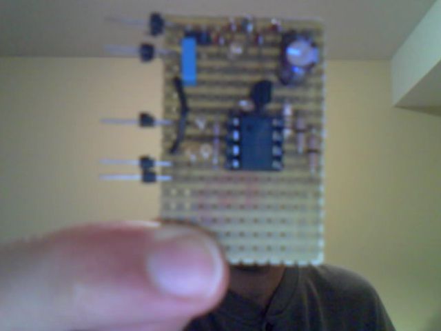
This is a signal generator that I made from a XR2206CP. It's a percision multi-signal generator capable of providing signals up to 2 MHz. The circuit is literally wired from XR's datasheet. One problem is that as of Jan 2011 this product became obsolete, and is no longer available at digi-key.
The two potentiometers on the right control the high and low level of the amplitude. The two on the control the the frequency. Dip-switch 1 turns the circuit on. Switch 2 turns on the sine-wave, 3 gives a triangle-wave, and 4 gives a square wave. Since the IC is power by a single supply the waveforms will have a DC offset of Vcc/2.
It's a great thing to have arround. It can even be used as an FSK or AM modulator, but it requires a more sophisicated circuit than I can build with simple tools. An improvement would be a frequency meter that could display the frequency of the wave. Also, it would be cool if there was a way to show how distorted the output wave was for percision tuning without an oscilloscope.