
|
ME481/2 Design Project |
|
Physical Concept |

|
Auto Balancing Lathe |
|
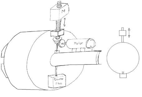
Any imbalance in a rotating mechanism can cause wear and tear on the machine. When machining with a lathe, the vibration from the imbalance can also cause imprecision in the manufactured part. The solution to balance the load on the chuck of the lathe and to reduce vibration is to use single plane balancing method, where the balancing mechanism moves and places a single mass in the opposite direction of the unbalanced load. The concept is to use a motor to drive a counter mass in the radial direction inside the rotating chuck mechanism, and the counter mass is manually positioned in the angular direction. Due to the cost constraint of this project, the angular positioning of the counter mass cannot be automated. Power to the motor is transmitted using slip rings, to allow the motor to rotate within the chuck mechanism. A vibration sensor is used to detect the imbalance and inform the operator the angular position of the imbalance.
Vibration caused by rotation of the unbalanced load produces periodic force acting on the mechanism. Theoretically, the frequency of vibration should be the same frequency as the rotation of the chuck. The vibration sensor is placed on a stationary part of the lathe to detect and record the vibration. The signal is compared to a periodic reference signal also with the same time period as the rotation. Based the time interval between the peaks of vibration to a reference point, the angle of imbalance with respect to the chuck is calculated.
The magnitude of the force due to imbalance and the radial position of the counter mass are calculated below. However after the angular position of the imbalance is determined, the motor can drive the counter mass by trial and error to find the radial position, from the vibration sensor feedback.
|