


|
ME481/2 Design Project |
|
Mechanical Design |
|
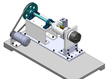
In order to allow maximum availability for variation and customization it was decided that a custom spindle would be made for this project instead of attaching it to an existing lathe. The lack of availability for existing lathes would also have been a limiting factor. The overall design is a motor and spindle assembly driven by a v-belt via pulleys. In-between the shaft and chuck connection is where the balancing mechanism will be attached. Figure 1 shows an overall isometric view of the system.
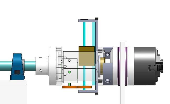
Figure 1: Mechanical Model As seen above the drive shaft is held in place by two self aligning spherical bearing pillow blocks. The shaft is driven by a large pulley and v-belt configuration. The entire assembly is built out of aluminum for ease of manufacturing and light weight. Because this is only a proof of concept there is no need for using longer lasting or more study materials such as mild steels. The transmission shaft is however made out of stress proof steel so it can withstand vibrations during testing and any applied cutting loads. The balancing mechanism chassis is also made out of aluminum since it is of much greater diameter and does not need to have a very long operational life for the purpose of this design demonstration. For simplicity the assembly is made out of standard stock sizes of plates, c-channel and L-brackets. For precision these parts are located with dowel pins and fastened down with machine screws. This will ensure proper alignment of the spindle assembly. The chuck purchased for this project is a 3 jaw metal working chuck however it can be used for mounting wood pieces as well or mounting a faceplate for wood. Because of the light construction of this assembly any machining tests will be done on wood and not harder materials. The chuck is mostly supported by a large bearing and then the chassis of the balancing mechanism. Figure 2 below shows a zoomed in and transparent view of the balancing mechanism.
Figure 2: Balancing mechanism As seen in figure 8 the balancing mass can move up and down the guide rail to offset the spindle. This is driven by a stepper motor that drives the lead screw via spur gears. The benefit of allowing the mass to pass through the center of rotation is that no counter balancing mass is needed. If the spindle is unloaded the balancing mass will retract to the center of the drive shaft and remain there. This removes the need for keeping a constant counter mass to balance out the offset weight of the screw and screw holder since the balancing mass can retract past center and create equilibrium. When the chuck is loaded with an unbalanced part the mass can move out to counter balance it. This however requires a preliminary step of aligning the guide rail with the unbalance. This is done by loosening the rotational wedge lock, then spinning the chuck relative to the guide rail to the desired location and locking the rotation lock. The exact location will be determined via electronics, more on that in the next section. The rotation lock is a friction based locking system. It is tightened by a long screw that goes through the center of the chuck mounting brace. When the screw is tightened it presses together the two semi circular pads and prevents the chuck from rotating relative to the guide rail. This system allows for a brass mass of 1.7lb (770g) to move 4 inches (101.6mm) creating a counterbalance moment of 6.8 in*lb. This mass can be replaced with a longer and heavier mass if required. Nevertheless the designed system will be able to counterbalance up to 1.7lb at a maximum distance of 4 inches from the center of rotation. For full design specification refer to Appendix A. Appendix A includes all part and assembly drawings with materials and tolerances selected. For detailed information on motor power calculation refer to Appendix C. For a list of required materials and purchased components refer to appendix B. |

|
Auto Balancing Lathe |