Supplement to 2.5.1 Horizontal Pathways and 2.7 Building Structure Considerations
Horizontal pathways are the routes taken for the installation of cable from the telecommunications closet to the work area. The pathways can be composed of cable tray, conduit, underfloor duct, and ceiling spaces. Ceiling spaces are considered the enclosed areas between ceiling tiles and the roof or upper floor. In cases where there no ceiling space, than conduit or plastic duct will be used to circumvent this problem. All conduit and ducting shall be attached as per UW plant standards.
All new cable installations must use CAT 5e UTP Plenum rated cable. Category 5E (Enhanced Category 5) is the next higher grade of UTP beyond Category 5. The Category 5E specification has been developed to provide more robust support for 1000Base-T. Category 5E will specify tighter limits than Cat 5 for NEXT, ELFEXT and Return Loss. This cable is to have a purple jacket so differentiating it from CAT 5 cable can be easily made.
Hardware including cable, connectors, patch panels, etc., should be the type approved for use by the CCIC (Campus Cable Infrastructure Committee) and Engineering Computing. The Panduit Pan-Net and Pan-Way line of products are to be used. The majority of the hardware required for your project can be purchased through IST.
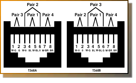
CCIC and Engineering Computing have adapted the use of type 568A wiring standard for these connectors. If a crossover cable is needed, use the 568A standard on one end and 568B on the other end.
J-Hooks and Fire-Stopping
J-hooks and FireStop can be acquired from IST or from Engineering Computing at no cost.
After the installation is complete a request to have the lines certified is to be made to Martin (Faculty Technical Consultant). A visual inspection will also be made at this time.
All new cable must be certified to the minimum TIA-568B standards. This is a new standard release that updates and replaces the following standards and bulletins: TSB67, TSB72, TSB75, TSB95, TIA568A, TIA568A addendum's 1,2,3,4, and 5, and TIA ScTP (PN-3193 Interim standard).
Certification is based on CAT 5e testing standards. The following properties are to be tested.
Wire Map – The wire map test will detect and report wiring failures or cabling defects such as:
a) continuity;
b) short circuits between any two or more conductors of the wires tested;
c) transposed pairs between any of the pairs tested;
d) reversed pairs;
e) split pairs among the pairs tested.
Wire Length – The length of each link should be recorded in the administration system ANSI/ TIA/EIA 606 standard or EN50174 Part 1. Used in measuring attenuation.
Attenuation – All electromagnetic signals lose strength as they propagate away from their source, and LAN signals over cabling are no exception. The loss of signal strength in the cable is attenuation. The more attenuation you have, the less signal is present at the receiver. Attenuation
increases with both frequency and length.
NEXT – When current flows in a wire, an electromagnetic field is created which can interfere with
signals on adjacent wires. As frequency increases, this effect becomes stronger. Each pair is
twisted because this allows opposing fields in the wire pair to cancel each other. The tighter
the twist, the more effective the cancellation, and the higher the data rate supported by the
cable. Maintaining this twist ratio is the single most important factor in any successful UTP
installation.
Delay Skew – Propagation delay skew (skew) is the difference between the propagation delay on the fastest and slowest pairs in a UTP cable. Some cable construction employ different types of
insulation materials on different pairs. This effect, in addition to unique twist ratios per pair,
contributes to skew.
Propagation Delay – Propagation delay, or delay, is a measure of the time required for a signal to propagate from one end of the circuit to the other. Delay is measured in nanoseconds (nS). Delay is the principle reason for a length limitation in LAN cabling.
PS NEXT – Power sum NEXT (PSNEXT) is actually a calculation, not a measurement. PSNEXT is derived from an algebraic summation of the individual NEXT effects on each pair by the other three
pairs. PSNEXT and ELFEXT are important measurements for qualifying cabling intended to support 4 pair transmission schemes such as Gigabit Ethernet. There are four PSNEXT results at each end of the link per link tested.
EL FEXT – ELFEXT is a calculated result, rather than a measurement. It is derived by subtracting the attenuation of the disturbing pair from the FEXT this pair induces in an adjacent pair. This normalizes the results for length.
PS ELFEXT – Power sum ELFEXT (PSELEXT) is actually a calculation, not a measurement. PSELEXT is derived from an algebraic summation of the individual ELFEXT effects on each pair by the other three pairs.
More detailed definitions are available at