System Architecture
The proposed design is a system capable of converting user input into a physical representation of the virtual profile. The first component is a tablet PC where the user can draw any non-intersecting line. The software discretizes the user input into a series of actuator angles. Next, these angles are distributed to the Arduino Duemilanove microcontrollers connected to the PC through USB.
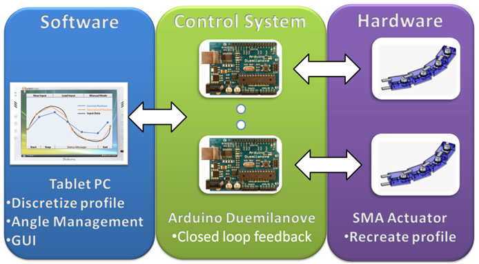
The Arduino Duemilanove is utilized to implement a closed loop feedback system for up to 5 actuators. The PI controller utilizes the error from the reference angle and current angle, which is measured by a potentiometer voltage. The output from the controller is a voltage which is converted to a high current value through a transconductance amplifier configuration. This current heats one of the two shape memory alloy springs in the actuator which causes rotation in the desired direction.
Due to limitations of existing actuators, shape memory alloy is utilized in the design of a new actuator which is capable of providing the required torque while maintain low overall dimensions. The current actuator angle data is transmitted back to the tablet PC where it is utilized by the graphical user interface(GUI). Not only does the GUI handle user input, but also displays an updating image of the current actuator positions moving into the discretized locations. Thus, the device allows a user to draw an image and watch it appear in real-time. An analysis of the detailed design is contained in the following sections.
Mechanical Design
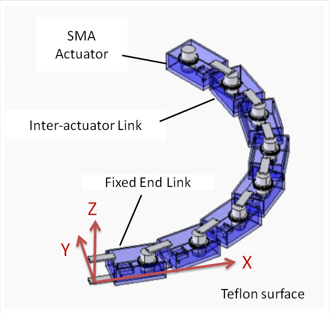
By analyzing the project constraints and criteria for alternative designs, it was determined that the rigid link design concept with memory shape alloy is the preferred design. The proposed device consists of a number of rigid links interconnected in series at rotary joints. With the end link fixed to a low friction PTFE (Teflon) surface, the rest of the links are free to move. By controlling the joint angle of each rotary actuator, the entire device can be bent in to arbitrary shape.
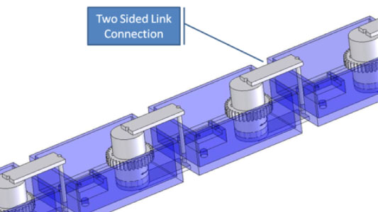
The SMA actuator chain consists of a number of SMA actuators connected with a two sided link connection for added stability and load distribution. The designed actuator is capable of moving 25 of its neighbours under the worst case scenario (all link chained in a straight line result in max mass moment of inertia). While it is unlikely that 25 links will be fabricated for the symposium, it demonstrates that the proposed actuator can produce enough torque to drive a device of this scope and size, and its potential for additional expansion.
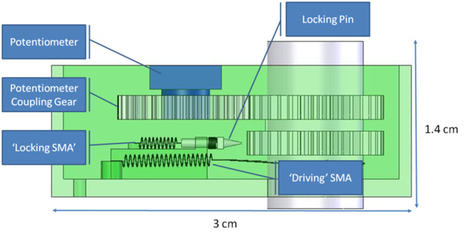
The design for the SMA actuator incorporates the SMA spring differential drive for shaft rotation. In this design a potentiometer is used for shaft rotational position feedback. Also included in this design is a locking mechanism to hold the shaft in place when it is not being driven. When the SMA locking spring is not excited, the bias force spring engages the locking pin with the drive shaft gear. This holds the drive shaft in place. This allows for the device to provide holding torque on the load, with no power input to the system. In order to drive a load, the locking pin must be disengaged.
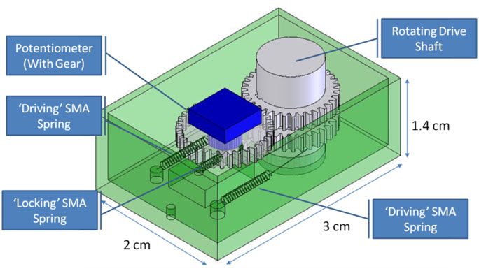
When the locking SMA spring is excited, the entire locking pin is retracted. During this phase, the driving SMA springs can be used to rotate the drive shaft. Once the shaft has settled at the desired position, the excitation is removed from the locking SMA spring, thus allowing the locking pin to engage with the drive gear, holding the shaft in place.
Controller Design
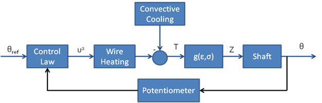
The SMA wire is extremely difficult to model since there are many non-linearities in the system and complex characteristics which change when the material is heating up or cooling down. As a result, a simplified control strategy is employed, with the use of a Proportional Integral controller. Researchers working with feedback control using SMA actuators have had reasonable success with this type of control law[1].
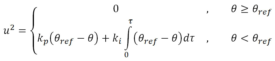
The desired angle is sent into the controller which outputs the appropriate current values. The current is used to heat the wire where some of the heat is dissipated through convective cooling, while the remainder is used to drive the SMA contraction. This linear displacement of the SMA is kinematically constrained to the shaft rotation. The movement of the shaft is captured by the feedback potentiometer, which completes the closed loop control.
Software Design
The software design is based on 4 key components. In order to recreate the physical representation of user input, the host computer software must first convert the image into a series of discretized joint angles. Since the physical system contains an arbitrary number of Arduinos, each with an arbitrary number of connected actuators, the next critical step is distributing the discretized angles to each Arduino. This process is handled in the angle management component which divides the angles into subsets for each Arduino.
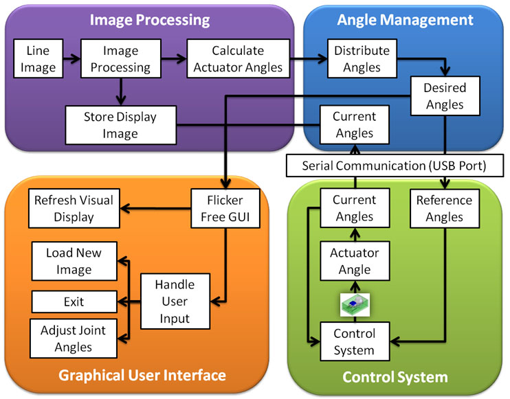
The subsets of angles are sent to the Arduinos through serial communication which utilizes USB ports and a standardized communication library. The closed loop feedback system is implemented solely on the Arduino hardware. The discretized angles are utilized as inputs for each joint controller and the outputs from the process are the current joint angles. These angles are sent back to the host computer through the same serial communication link.
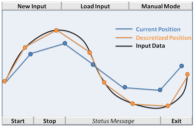
The purpose of transmitting the joint information back to the host computer is to allow the current position to be displayed on the graphical user interface. The GUI is the last component of the software design and it is responsible for displaying all information to the user, as well as processing any user events. User events consist of everything from the user changing the input profile to the user requesting the system to exit. Furthermore, the information displayed to the user also includes the original input profile and the desired discretized positions.
References
[1] Professor Robert B. Gorbet, University of Waterloo, Personal Communications: Design Project Status Meeting, Waterloo, ON, November 6, 2009.
[2] Oladele O. Owodunni, Javier Diaz-Rozo and Srichand Hinduja, "Development and Evaluation of a Low-cost Computer Controlled Reconfigurable Rapid Tool", Computer-Aided Design and Application, 1-4, 2004, 101-108.
[3] Brudnicki , M. B., "Rotary Actuator", 1995, US Patent 5,396,769.
[4] Trika, S. T, "Method and apparatus for progressively constructing a series of morphs", 2002, US Patent 6,362,833.
[5] Goldstein, Seth Copen and Mowry , Todd C., "Claytronics: A Scalable Basis for Future Robots", IEEE Computer, 38(6):99-101,June, 2005.
[6] Dickenson, Carrie. Wen, John. "Feedback Control of a Shape Memory Alloy Actuator", Journal of Intelligent Materials and Structures. April 1998.