
Pictures of the Symposium and First Touch Machine Construction
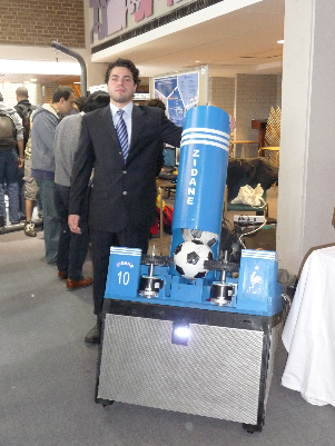
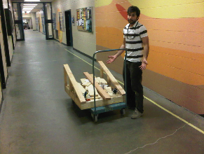
Mark G. looking sharp beside the FTM
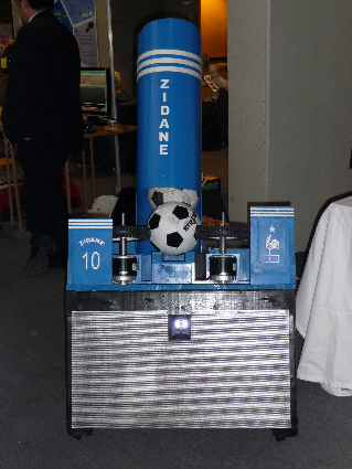
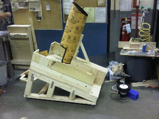
A side-view of the FTM while Mark G. quenches his thirst
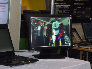
The Vision System display in action the Vision System detected the red shirt held by Azam J. (shown in the screen) and drew a box around it
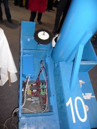
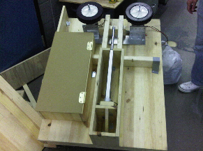
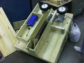
A top-view of the electrical box encasing all of the electrical components including the battery, motor controllers, linear actuator controller, and the Microcontroller Board
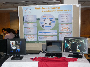
The FTM Project booth at the 2010 Symposium with the project poster displayed in the back.
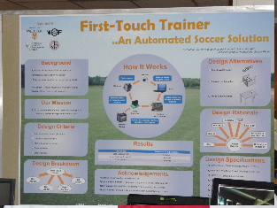
A closer look at the FTM Project poster
The webcam with its white LEDs on the FTM was actively looking for the color red in its field of view
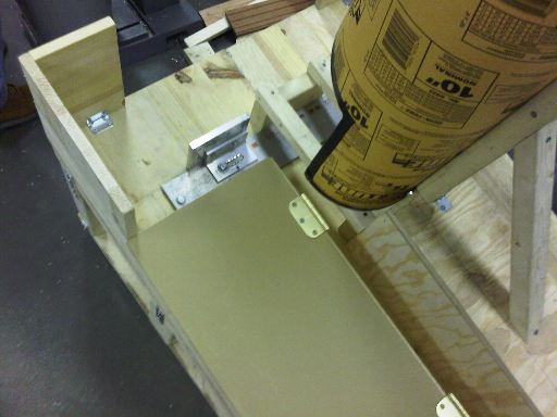
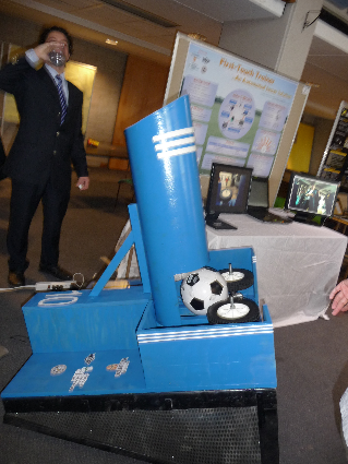
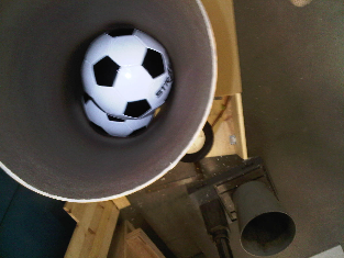
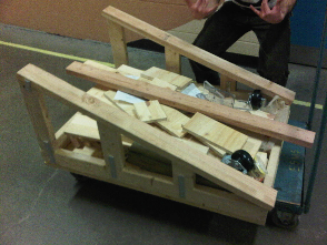
Image of the Hopper and Loader systems connected.
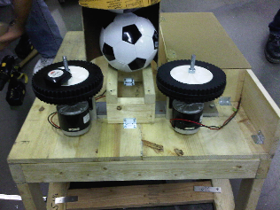
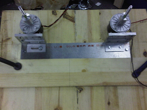
In this image adjustments were made to the motor component locations to achieve optimal ball launching conditions.
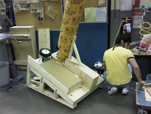
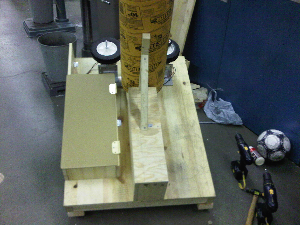
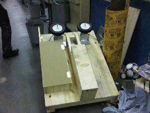
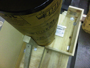
The Linear Actuator used to load the ball into the Launching system was covered due to aesthetic and safety reasons.
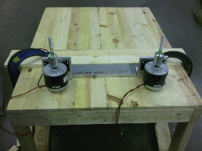
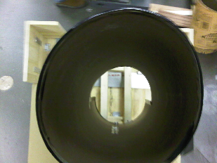
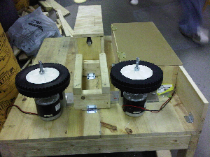
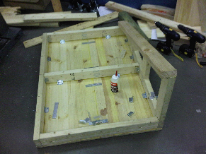
In this image, the motors are being centered with respect to the base structure and then fixed to the base structure.
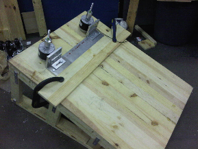
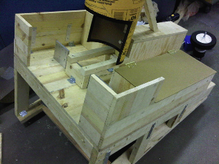
Base structure completed (shown upside down in image).
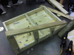
The base structure was constructed using an endless supply of wood, screws, flat brackets, L-brackets, and Carpenters glue to ensure a strong, sturdy base structure for the FTM.

Kick Logic
University of Waterloo
200 University Avenue West
Waterloo, Ontario, Canada N2L 3G1
519 888 4567
feedback | privacy statement | http://www.uwaterloo.ca