Personal Projects
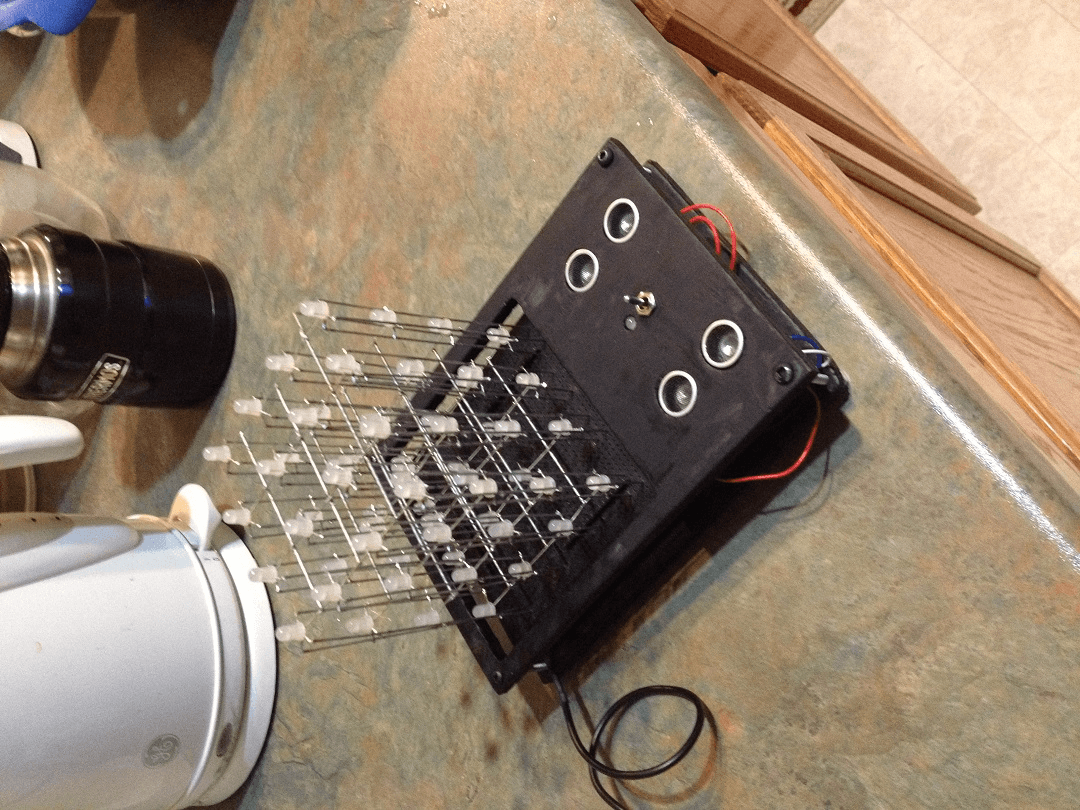
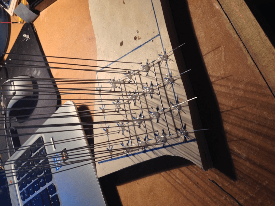
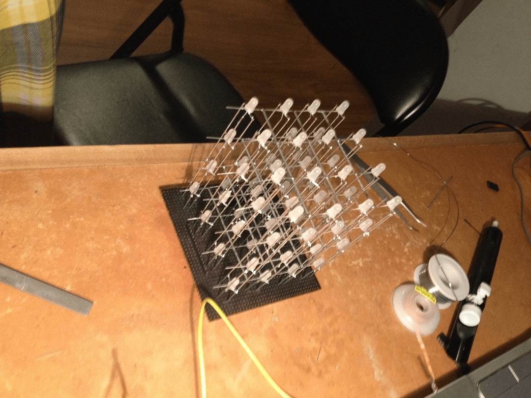
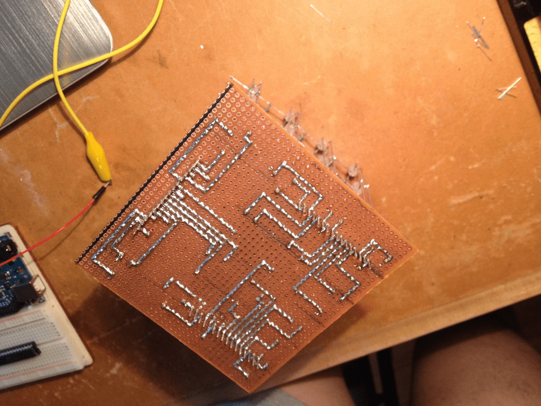
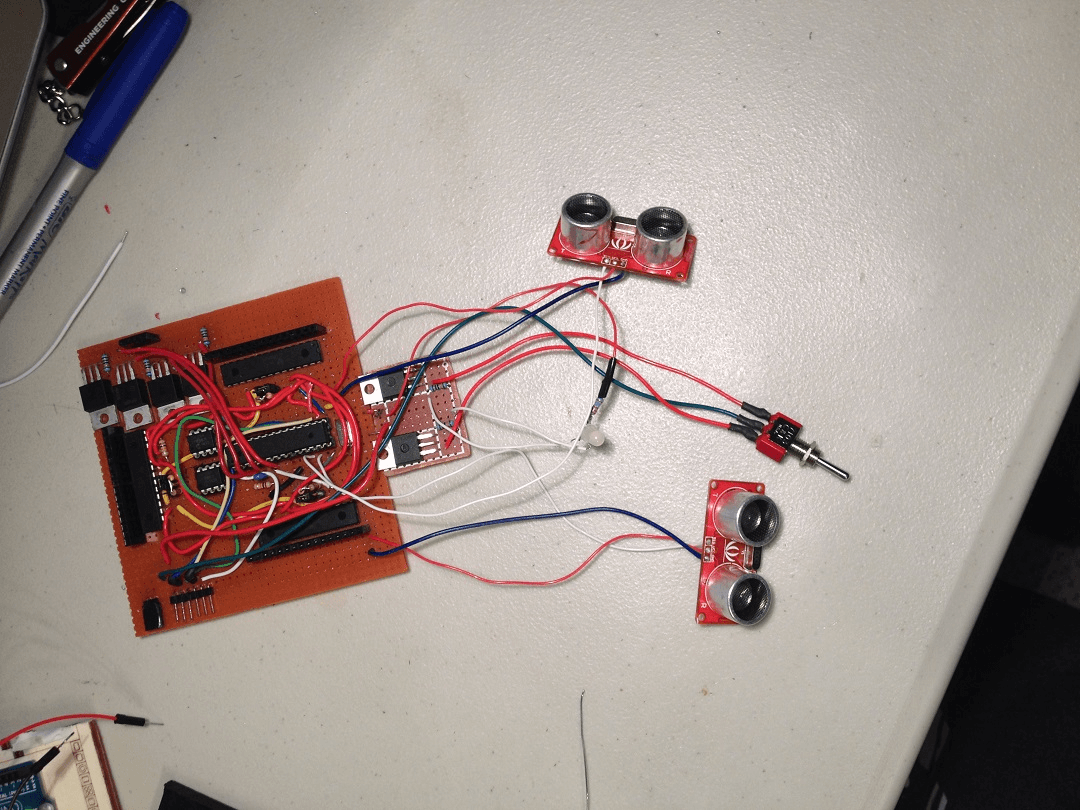
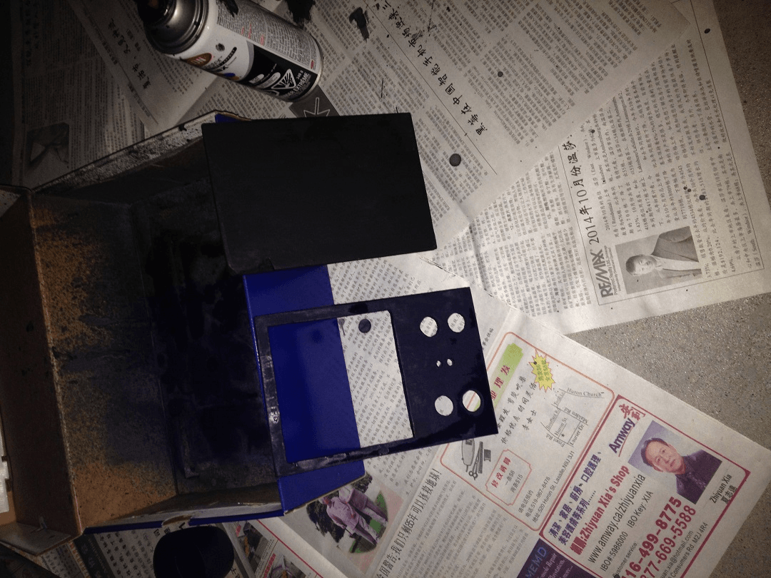
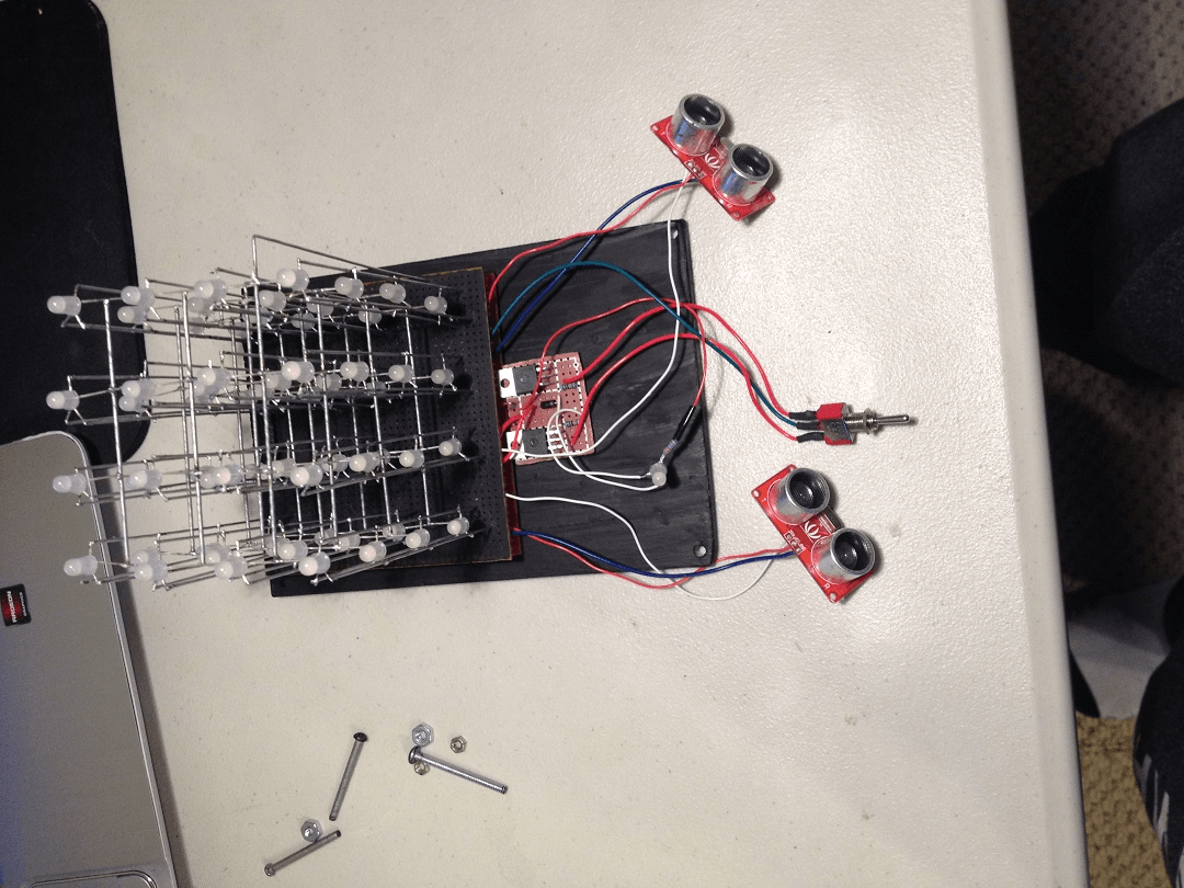
Sonar RGB LED Cube
4x4x4 RGB LED Cube with built in sonar sensors to allow motion controls.
Completed Details
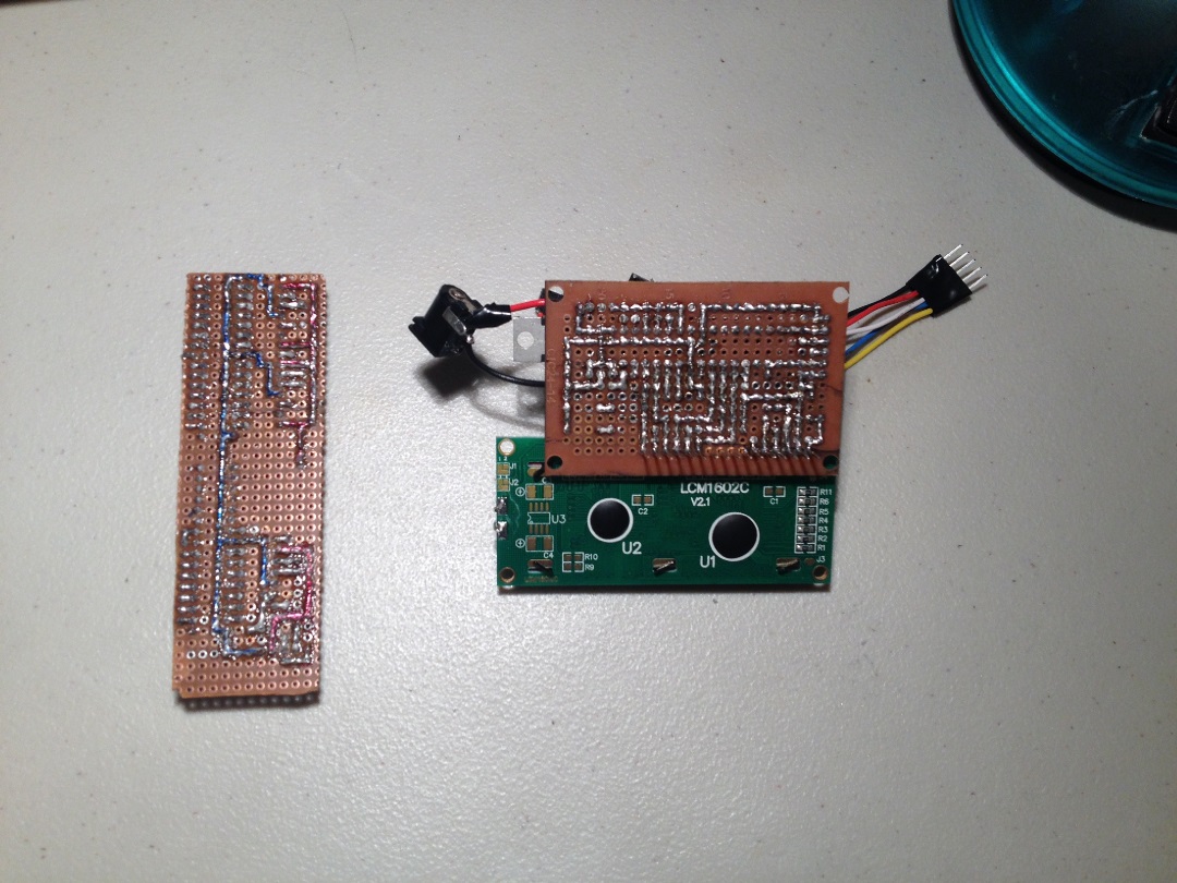
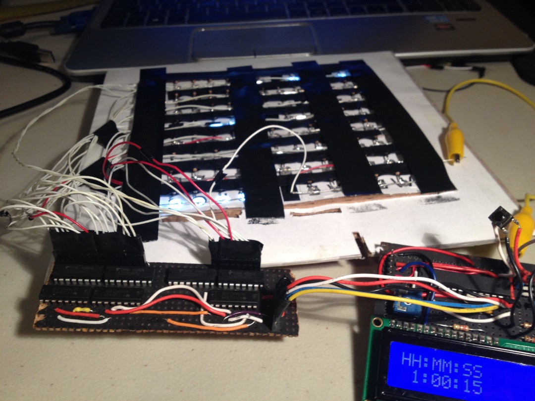
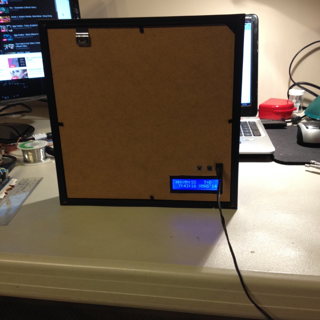
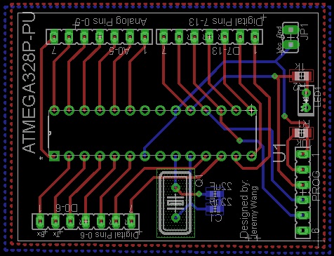
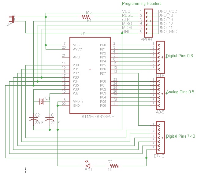
Minimalist Arduino UNO
Barebone Arduino UNO PCB created with the ATMEGA328P-PU chip.
Completed Details
Old Wooden Bluetooth Music Player
A bluetooth music player made by using the speakers on an old wooden radio and a PAM8403 audio amplifier, both controlled through the Raspberry Pi. An additional webcam is used to filter live video to provide gesture feedback controls.
In Progress Details
SPOCK - Smart Padlock
A padlock integrated with a biometric finger scan sensor from SparkFun and small servo motor allowing users to access the lock with a simple touch of their finger.