


Design Overview

Mechanical Design Overview
The mechanical design consists of the chassis and the recovery system.Chassis Construction
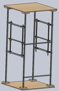
Using 6061 aluminum the chassis is constructed out of tubing that are attached together using solid pieces. To provide a flat surface to perform the squat on, plywood was attached to the bottom. This is what the design of the chassis looks like: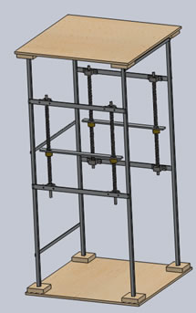
Recovery System
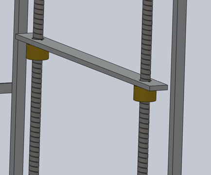
The aluminium connecting the lead screws acts as the safety bar where the user can drop the weight, and this is the primary component of our recovery system. When a user goes into a bad state, these safety bars are moved upward until they have safely captured the squat bar.The recovery system is driven by two motors; each motor drives one side of the recovery system. Each side contains two lead screws and both of these lead screws are driven by a single motor; to ensure proper vertical translation of the mechanism and to eliminate binding. Slider mechanisms are attached to the squat rack to withstand horizontal forces on the recovery mechanism. All components are bolted together except for the linear slider mechanism which is threaded into the ends of the safety mechanism.
Lead Screws
ACME lead screws were selected to prevent back drive, allowing users to abuse the safety bar without causing the system to fail. These lead screws were generously donated by Threadall Manufacturing.Drive Train
The drive train consists of PowerGrip rubber synchronous timing belts with aluminum pulleys. These belts help reduce noise while ensuring slippage is minimized. Gates PowerGrip line was chosen for its reliability.Motor
Using a Permanent Magnet DC motor we are able to deliver the power required to lift heavy weights, allowing the design to be used by most weightlifters. A 1/3HP is used for demonstration purposes, and a much larger motor will be used in production. Bodine motors were selected for their value and robustness.
Electrical Design Overview
Electrically there are two main components, the Kinect's RGB camera and 3D depth sensors and the motor controller.Joint Tracking
Depth sensors onboard the Kinect can accurately locate the user within its field of view, allowing every joint to be accurately tracked throughout the excercise. To see how others are using the Kinect, check out Kinect-Effect.Motor Control
After the system identifies the need to activate the recovery system, the motor control mechanism delivers the signal from the computer to the motors. This portion of the system enables teh recovery to occur.
Software Design Overview
Software consists of the feedback system and joint tracking interface.Feedback System
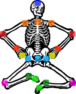
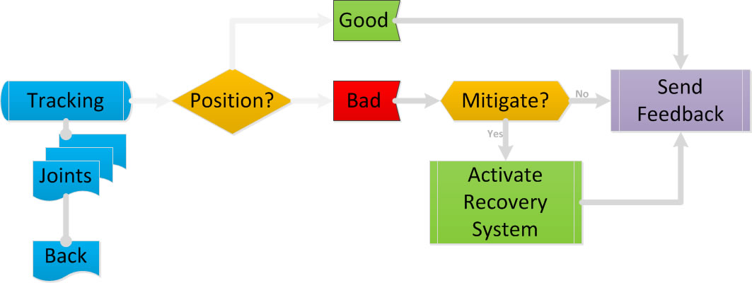
The real-time feedback used is to help the user remain in a good posture and warn them when they are in a bad posture. The image is computer generated based on the positions of the joints. An overall status indicator tells the user what state he/she is in. Green indicates that the posture is good, yellow indicates the posture is bad, but recoverable, and red indicates the posture is in a dangerous and irrecoverable position. The joints change colours based on their status as well.Joint Tracking
Major joints on the body are tracked by the Kinect and then analyzed using our joint tracking algorithm. Whenever users deviate from a good position, the algorithm begins the warning or recovery process.