Latest News
Symposium Day! We had everything working as it should have and presented to many interested atendees. Great to finally show off our work and get feedback!
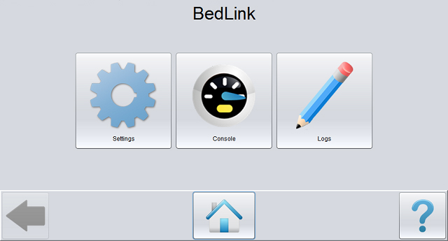
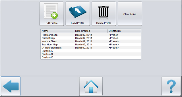
Santosh has been working on a PC application that allows the user to manipulate tilt profiles, retrieve activity logs, control the bed, and customize behavior. We were careful to keep our user demographic in mind. User interface design principles were used to cater to an audience that is less comfortable with technology.
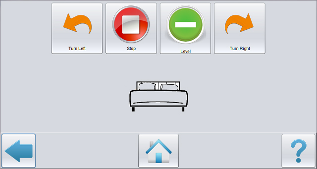
While the primary mode of operation for our system is automatic, a user console is critical due to safety and user experience consideration. We fabricated a console with buttons to tilt the bed to the next left or right increment, or to return the bed to a level position. There is a seven segment display used to show the current tilt angle of the bed. There's also an alarm button that activates the buzzer and an auto toggle which puts the system into automatic mode. The seven segment display acts as a scrolling screen to select the tilt profile when in auto mode.
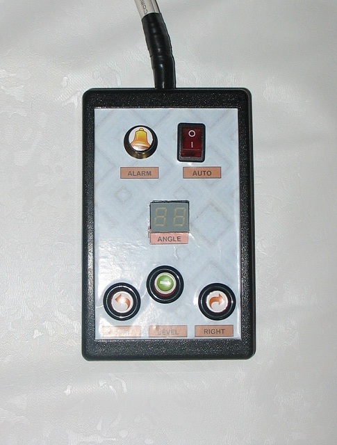
We used ethernet cables to connect of the button input circuits and display output circuit to the arduino.
Accelerometers have been acquired and we've characterized the output profiles. The fidelity of the sensors wasn't quite what we had hoped for so we took great care to come up with an accurate input-output relationship. The good news is that there is very little noise and we can reasonably expect steady and repeatable values at all orientations. We'll be building calibration functionality into the control system to account for variation due to changing environments. We are using two accelerometers to take differential angular measurements of the bed (one between each jack pair). This way we'll be able to minimize torque developed as a result of different actuation speeds of the jacks. Data from these sensors will form the basis for our control system.
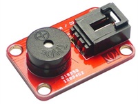
Aside from these sensors, we have also interfaced a buzzer to that can either be activated during an emergency by the system automatically or by the user through a console (more on that later).
The team has been working on the construction of the bed over the past week and we are finally at the point where we have a unit to show for our efforts. For the purposes of the symposium, we decided to construct a scale model of a twin sized bed. The constructed bed is made for a crib sized mattress (55inX34in). The decision to use a scale model was taken based on a number of consideration including portability and emphasis on control aspect of the project. The frame of the bed is actually quite simple. Made of wood, it is sturdy enough to easily accomodate our weight requirements and it simplicity allowed us the flexibility we requied in case of unforseen requirements for design changes.
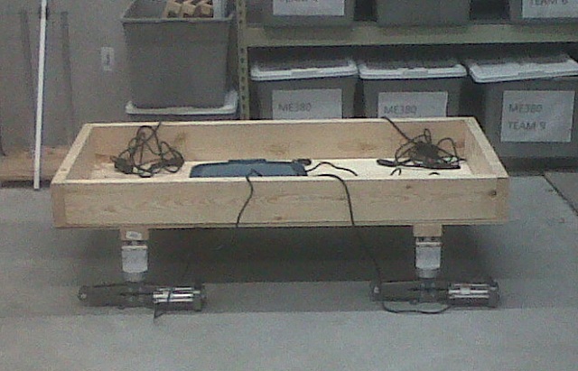
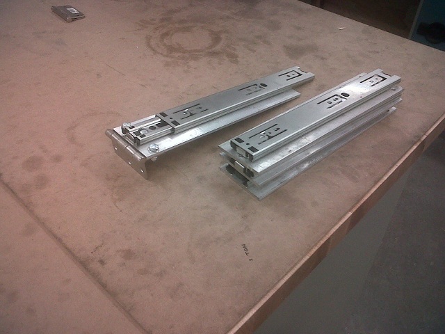
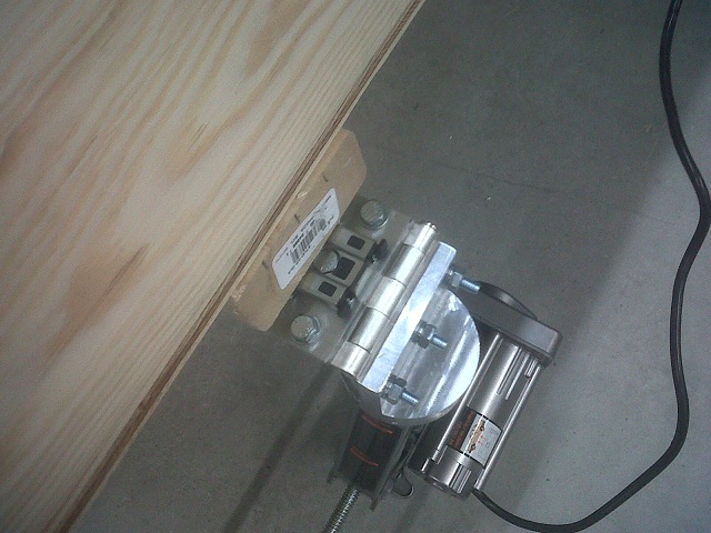
There are some attachments to that bed that are worth noting however. We used slider mechanisms at the four interface to the jacks to compensate for lateral forces generated when the bed is in a tilted position. The basic idea here is that the jacks are stationary and inflexible meaning they will be pulled inward when the bed tilts because the edge fo the bed will move inward (think trigonometry). By installing slider mechanisms that pull the jack interface out away from the edge of the bed we essentially eliminate the lateral forces on the jacks that would have caused instablity. Heavy duty sliders were attached to the underside of the support studs on the bed. Metal plates attached to these sliders act as the interface for the hinges which will eventually attach to the jack-coupler assemply. The couplers were designed and fabricated after inspection of the jack. These are attached to the top of the jacks while the top part can be bolted to the hinges attaching to the bed frame. Lastly, instability concerns prompted a decision to mount jacks onto plate plate which act as as a stablizing factor eliminating the danger of the jacks toppling.
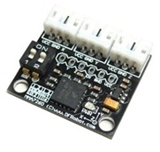
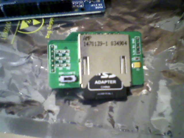
We started work on the data logging module of the system. We got a Seeedstudio SD Card Shield for data logging and storing configuration settings on an SD card. The module interfaces with the Arduino using the SPI interface. The SD Card Shield was built to be compatible with Arduino boards which have their SPI interface on pins 10-13. However, on the Arduino Mega, the SPI pins are 50-53. We thought this meant we would have to make some hardware changes to the Shield. However, the Arduino supports software SPI as well. Conveniently, there exists an Arduino library for FAT16/32 (sdfatlib) which also allows us interface with the card using software-based SPI.
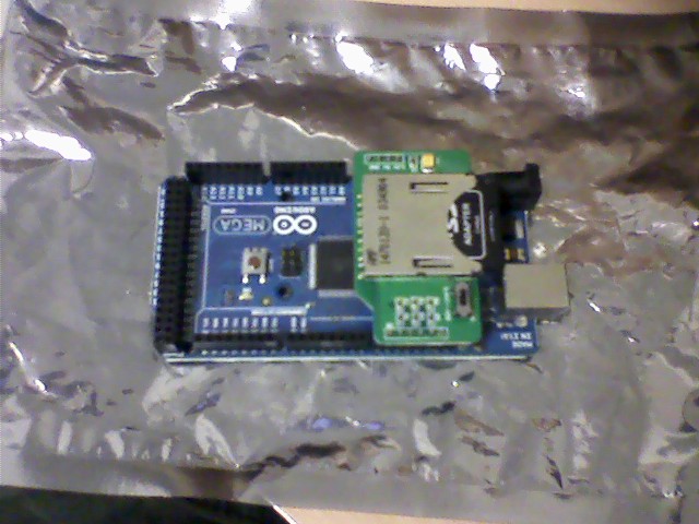
This is the SD card module from SeeedStudio. It plugs neatly onto the Mega.
The read and write sample sketches that came with the library were tested. The software-SPI was expected to have performance issues, but there was no noticeable lag in read/write. We will not be writing and reading a lot of data anyway, so it shouldn't be a problem.
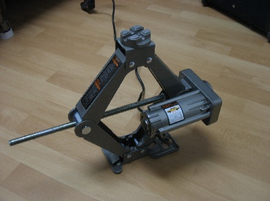
We used a single jack to lift up a bed (metal frame, box spring and mattress). The test was intended to make sure the jack has the lifting capability we require. It worked without slowing down, but the motor became considerably noisier. We will need to muffle the motor in some way. Since two jacks will be used to hold up the weight of the bed (and a human) the motors will not be as taxed, but some noise increase is expected.
The test was conducted without any support or permanent fixture to the bed, so as expected it wasn't very stable. Once the jacks are attached to the bed frame using a hinge, it should be stable enough for use in a home environment.
We successfully controlled the up/down motion of the jack using the Arduino. The emitter and collector pins of a 2N3904 NPN transistor were connected to the two pins of the push button (on the existing controller for the jack), and the base was connected to a digital OUT pin on the Arduino. A simple sketch that turned the digital OUT pin on and off in 2 second cycles was tested. The jack worked as expected. We will require 2 of the transistors per jack (one each for up and down motion).
We're figuring out power supply issues with the jack. Powering a 12V DC motor with a rated current of 11 A isn't as easy as we thought it would be.
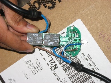
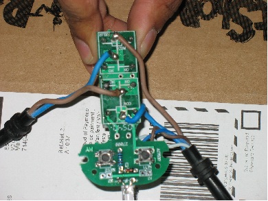
We opened up the controller on the jack and it seems relatively easy to control using the Arduino. It consists of two relays and push buttons that activate them. We'd need to activate the relays using digital outputs from the Arduino. Consultation with the MME electronics advisors has proven very helpful.
We're starting to acquire material to begin fabrication of the various components. Before we can get to that though we need to do some work fully characterizing the characteristics of the components. This part feels slow but decisions made here will be crucial down the road.
Welcome to the status section of our fourth your design project. Check this space for updates on our progress.