Final Design
This design is a system that is capable of converting user's virtual profile into a physical representation. The first component is a tablet PC where the user can draw any non-intersecting line. The software discretizes the user input into a series of actuator angles. Next, these angles are distributed to the Arduino MEGA microcontroller which is connected to the PC through USB.
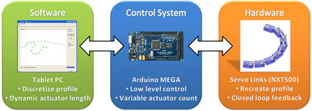
The Arduino MEGA is utilized to control 13 micro-servos which are connected in series with a rigid link design. Each micro-servo utilizes closed loop control to move to an angle between 0 and 180 degrees. These components work together which allow the user to draw any line on the PC and watch the physical representation form in front of them.
Although this design allows for recreation of any 2D profile, the shape reproduction accuracy is limited by the size of the micro-servos. Due to this limitation, shape memory alloy(SMA) is utilized in the design of a new actuator which is capable of providing the required torque while maintain low overall dimensions. The result is an SMA actuator which is smaller than the only SMA actuator on the market, provides seven times the amount of torque, and most importantly, utilizes closed loop feedback for angle control. This is the significant innovation resulting from the project and it is potential patentable and the team plans to investigate obtaining a patent.
Shape Memory Alloy Actuator
Shape memory alloy (SMA) is a smart material which can be easily deformed at room temperature and returned to their original shape when heated. This unique characteristic is utilized by attaching two SMA springs on either side of a shaft, then by heating either spring a differential drive is created, as shown in Figure 3. The springs are heated electrically by applying current through the individual spring.
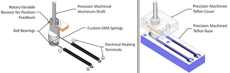
Bearings are placed at the upper and lower sections of the shaft to allow it to rotate with minimal resistance. The shaft has a keyed section to allow a potentiometer to slide onto the shaft and provide rotational position feedback. There are also two grooved slots around the circumference of the shaft. These slots allow the SMA springs to wrap around the shaft without interfering with each other which provides a higher rotational capability. The base and cover sections are created with PTFE (Teflon) material to reduce friction with the surface, and its dimensions are 4.5cm long by 1.5cm wide, with a height of 4.7cm.
Controller Design
The initial design of the controller (or more specifically, the control law) planned to use a black box approach to controller design. That is, nothing of the dynamics is known, and instead attempt to tune a proportional-integral (PI) controller using an iterative approach such as Ziegler-Nichols ultimate sensitivity method. This was suggested initially due to the highly non-linear dynamics introduced by the hysteresis behaviour of the shape memory alloy.
The major issue with this approach is that the overall tuning method is iterative, producing unnecessary wear on the SMA springs. This is mainly due to step response overshoot, as when the controller is not tuned (i.e. too much overshoot), one spring would be attempting to stretch the opposing spring while it is still hot. This process can damage the spring and this risk must be avoided.
Thus, a deviation in design is required. This deviation entails performing a proper controller design using a simplified linear model of the SMA spring plant. The system step response is approximated as first order and this model is utilized to develop a PI controller.
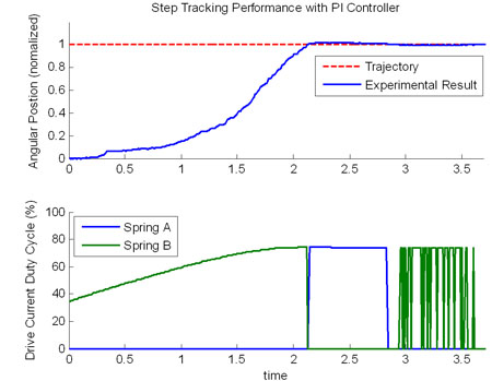
It is observed from the step response that the system achieves perfect steady state tracking with the PI controller. This is paramount for the application of this SMA actuator, as in the shape reproduction accuracy is highly dependent on the actuator settling exactly at the desired reference position. Furthermore, as expected, the non-linear dynamics introduce significant damping, decreasing the overshoot to approximately 2.2%.
Overall, the controller design, testing, redesign, and implementation is deemed successful, as the control scheme is able to position the actuator, which has highly non-linear dynamics, with perfect steady state tracking and minimal overshoot.
Software Design
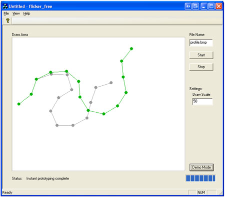
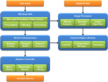
Another component of the system is the software which runs on a PC where the user can draw any non-intersecting line. The software discretizes the user input into a series of actuator angles. Next, these angles are distributed to the Arduino Mega microcontroller which is connected to the PC. The software design is based on four key components, each responsible for key functions.
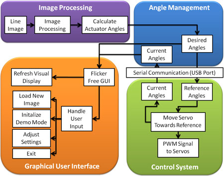
The main input to the software system is an image file which contains the profile drawn by the user. In order to recreate the physical representation of user input, the host computer software must first convert the image into a series of discretized joint angles. These joint angles are transmitted to the Arduino through a custom serial communication library.
The Arduino controls the angle or each servo and approximates the current angle since the closed loop feedback is contained within the servo. When the host PC requests a status update, the current angles are transmitted back to the host computer to allow the display of current positions on the graphical user interface (GUI).
The GUI is the last component of the software design and it is responsible for displaying all information to the user, as well as processing any user events. User events consist of everything from the user changing the input profile to requesting the system to exit. Furthermore, the information displayed to the user also includes the original input profile and the desired discretized positions. These software components comprise the initial software architecture.
Although there are 4 main components of the system, the actual implementation involves a combination of Windows API, existing libraries, and extensive custom code. A class overview highlights the key functionalities while identifying the commonly used helper libraries. Overall, the software successfully converts a profile image into key angles and transmits this information to each servo.
2D Profile Generation
One of the key components of the initial design is to utilized 10 SMA actuators connected in series to form any input profile. This provides a method of instant prototyping because the user draws any 2D profile in the software and the profile physically appears in real time. However, once the SMA actuator design is finalized, it is identified that it takes 2 days to manufacture a single SMA actuator. Due to limited access to the student machine shop, and limited timeframe, it is not feasible to create 10 actuators within the project timeframe. As a result, alternative actuators are investigated, and it is determined that utilizing micro-servos achieves all project objectives.
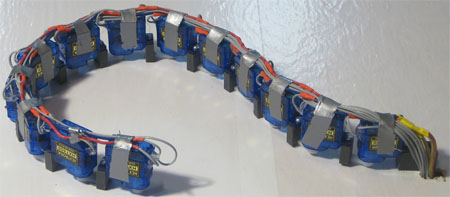
The Hextronik HXT 500 micro-servo is selected because it is one of the smallest servos on the market and it provides the required torque and closed loop control. The size of each servo is only 22.9 mm x11.4 mm x22 mm and they output 0.8kg-cm of torque. 13 servos are connected by fixing a rigid link between the actuation point and adjacent servo. This configuration is very similar to the proposed SMA actuator rigid link design where the only difference is the method of actuation.
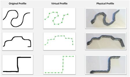
The profile generation is tested by analyzing the shape reproduction accuracy of a few arbitrary profiles. An image is drawn in paint and the project software is utilized to convert the image into a series of angles which are transmitted to each servo. It can be observed that the virtual profile is a relatively close approximation of the original image. Furthermore, the physical representation matches closely to the virtual and original profiles.
There are a few limitations to the servo implementation. Firstly, the servos only provide a maximum +/-90 rotation, and as a result, angles greater than 90 cannot be recreated. Another issue is the base servo motor must move the entire mass of servos and this is the most probably point of failure. Similarly, the maximum rotation speed of the actuators, especially the base actuator, must be limited to minimize the risk of a servo failure. However, the system performed for over 4 hours during the symposium with only one minor failure due to a loose wire.
With respect to the design objectives, the system has the ability to create a 2D profile from user input and it can be reconfigured to desired profile in real-time. Lastly, the system is a low cost solution as the servos and required material costs $95.00. As a result, the final system achieves the key objectives and is deemed a success.