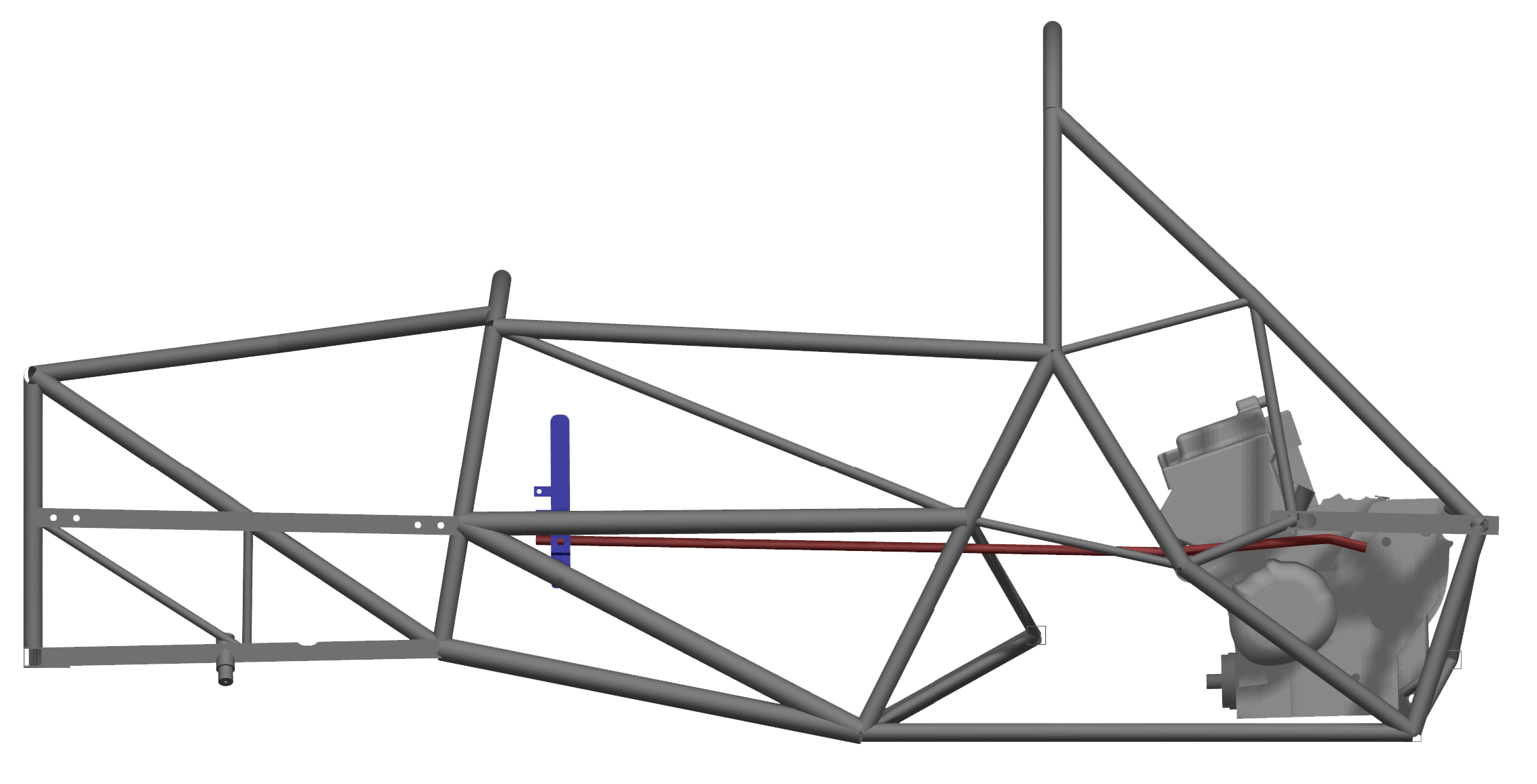
ShifterThe shifter mechanism is responsible for facilitating gear shifting as well as manual clutch control.
Gear Shifting
As part of the weight-saving efforts, the shifter mechanism was made entirely out of aluminum, accomplishing a weight reduction of 40% over past year's design. The mechanism consists of three main parts: the shifter handle, the hand clutch lever, and the linkage from the handle to the engine shifter lever-a 50% decrease in components over the past design. Since steel is naturally more reliable than aluminum, a route which allowed for the minimum bends in the linkage was chosen to minimize non-planar bending forces during shifting. However, a steel linkage will also be made as a back up in case needed during competition.
Manual Clutch Ideally, the clutch should fully disengage at the moment the handle clutch lever rests against the handle, allowing the driver to be sure of the status of the clutch without being worried about damaging the cable or other components of the system. To achieve this, a handle clutch lever length of 12mm was selected.
With such a large torque needed to turn the clutch, the handle clutch lever
was also designed such that the driver need apply 60N of force to operate.
Although this is significantly higher than the force needed for gear shifting,
it is within ergonomic specifications for the human hand. It is also natural
for the clutch to require more force than shifting to avoid any accidental
inputs. Because of the high force requirements and size limitations, the lever
was made out of steel for increased reliability against long-term fatigue.
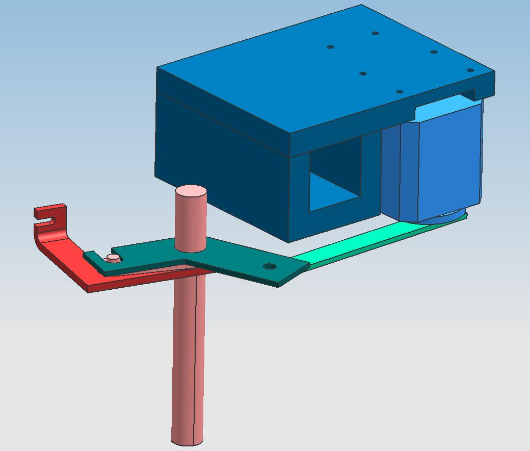
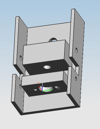
Servo Linkage There are two objective of these linkage. First is to transfer the force of the servo to the clutch barrel appropriatly. This is done by choosing the appropriate radius for the four bar system, allowing a torque reduction of 1:3. The second is to isolate any extra load from the hydraulic line actuated by the manual clutch handle. The original design did not incorporate this, and the servo experienced added load, decreasing performance. The drawback of isolating the servo from the manula system is there is no inherent system for the driver to know when the servo is active. In the previous design, the handle moved when ever the servo was actuating the clutch. From now on, the front lcd display will output clutch engagement. Speed Sensor
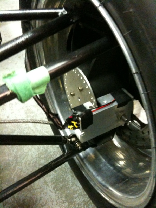
The current wheel speed sensor has a resolution of 3 pulse per revolution, or 120 degrees. To detect a 5% wheel speed difference between front and back, we have increased the resolution to 36 pulses per revolution or 12 degrees using an optical sensor. The optical sensor brought up another problem of dust. We have also implemented an induction sensor with 18 pulses per revolution. To fill in the first second of launch, where a speed sensor is not as effective, we are using an accelerometer in conjunction with the wheel speed sensor. |