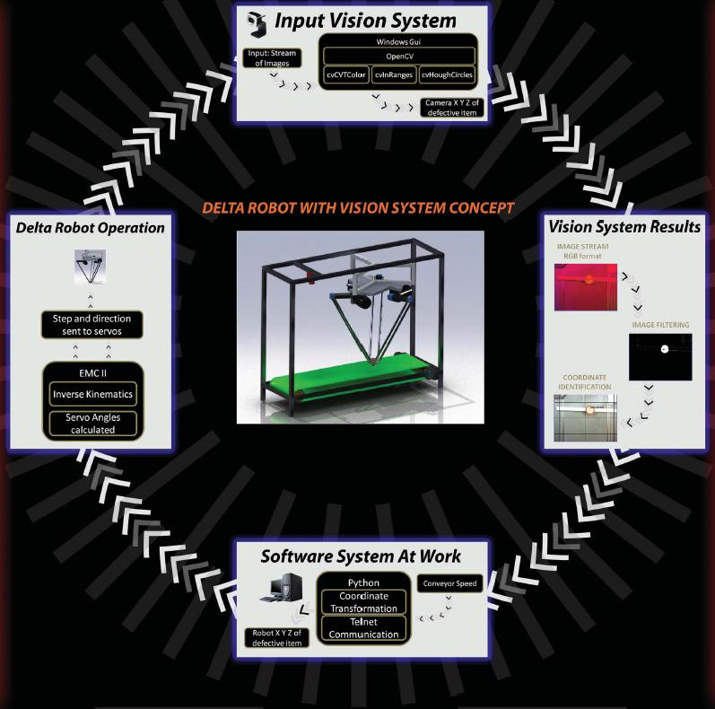
Operation Review
The proposed solution consists of the delta robot, vision system and a conveyor mechanism (which would be used for testing purposes). The vision system comprises of a camera which is interfaced with the computer through a USB cable. The camera sends images of the biscuits on the conveyor to the computer. The computer uses OpenCV algorithms in order to extract the biscuit images and compares the images with stored template images. In OpenCV, the coordinates of the defective biscuit are also calculated using the pixels of the camera. The speed of the biscuit is also calculated through the stream of images. The computer would then take the speed and use it along with existing coordinates of the defective biscuit to find the new position of the biscuit. This new position would be passed on to the delta robot in terms of coordinates. These coordinates are passed to the servo controlling software (EMC2) which uses inverse kinematics to calculate the servo angles and sends these angles to the delta robot such that the robot end effector can reach the targeted biscuit on time. The links of the delta robot are then oriented according to the servo angles passed and the suction is engaged. The robot picks up the targeted biscuit, new angles (which determine the location of the designated scrap bin) would be sent to the servo motors, the robot would release the biscuit in the scrap bin and return to its home position.
Return to Top
Delta Robot Specifics
Servo Motors
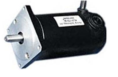
Three servo motors were used to actuate the delta robot mechanism. The motors were KL34-180-90 (Nema 34) DC Brushed motors from Keling Technology Inc coupled with AMT 102 encoders from CUI Inc. The figure below shows the KL34-180-90 DC brushed motor.
Servo Drives
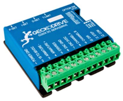
Three Gecko G320X DC Servo drives were used to control the servo motors individually. Gecko 320X incorporates a hardware level PID loop and abstracts the servo movement to step signal and direction signal. It is capable of operating at 20A continuous current at 80V DC. Also, it is able to support the AMT102 incremental encoder over the complete 48 to 2048 Count per revolution settable range. Figure below shows the gecko drive used.
Return to Top
Suction Mechanism
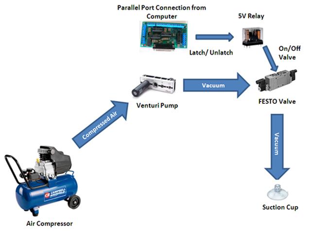
The suction cup mechanism is comprised of an air compressor, a Venturi pump and a FESTO type MFH valve. The air compressor was chosen to yield 75 psi at all times which was the optimum pressure required to operate the valve. The air compressor would blow air into the venture pump which generated a vacuum. The vacuum was controlled through a FESTO valve. The Festo valve was controlled through the parallel port using a 5V relay. The diagram below shows the details of the suction cup mechanism.
Return to Top
Electrical Interface
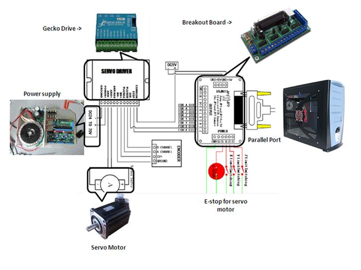
The diagram below shows the electrical wiring details of the servo control system. It shows the connections of the DC power supply, breakout board, gecko drive and servo motor. For simplicity only one motor interface is shown (the other interfaces are identical).
Return to Top
Servo Motor Controlling Software
EMC (Enhanced Machined Control Software) was used to control the servo motors. EMC is a software system for computer control of machine tools such as milling machines and lathes. EMC control can operate true servos (analog or PWM) with the feedback loop closed by the software at the computer, or open loop with "step-servos" or stepper motors. It is a free software with open source code.
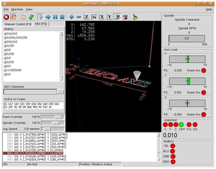
EMC was used to map the parallel port pins and also implement inverse kinematics equations. The inverse kinematics equations were written in C and compiled with EMC which allowed the software to take x, y, z as input and calculate servo angles. These angles were then passed to the servo motors through the parallel port. The figure below shows a screen shot of the EMC display.
Return to Top
Vision System Software Algorithms
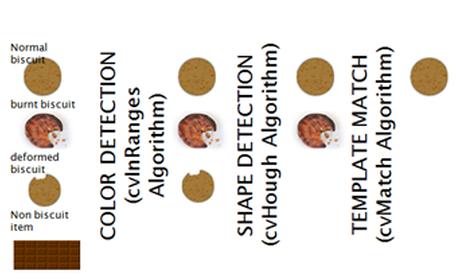
OpenCV libraries were used to implement the vision system. OpenCV (Open Source Computer Vision) is a library of programming functions for real time computer vision. Three algorithms were implemented for image filtering: cvColor & cvHoughCircles (to isolate biscuits from the image stream) and cvTemplate to compare the extracted biscuit images with a good template.
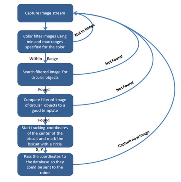
The chart below shows an overview of the software architecture.
The vision system was also used for speed calculation of each biscuit. The speed was calculated so that the coordinates of the biscuits could be updated real time while it is moving on the conveyor. These updated coordinates were passed on to the robot for pickup. The speed was calculated by identifying two points on the camera; as soon as the biscuit would pass the starting point, the CPU clock was noted and after the biscuit cleared the ending point the clock was noted again. The difference between these clocks and the distance between the starting/ending points was used to calculate the speed.
Return to Top
Camera Selection
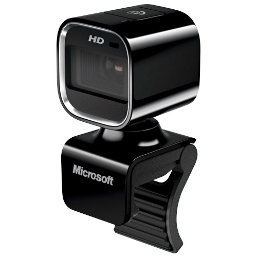
OpenCV works with certain types of cameras. Microsoft HD lifecam was chosen due its compatibility with OpenCV and a frame rate of 30 fps (which was sufficient to capture several images of the biscuit while moving on the conveyor). The camera was connected via USB to a computer which was running OpenCV.
Return to Top
Interfacing The Entire System
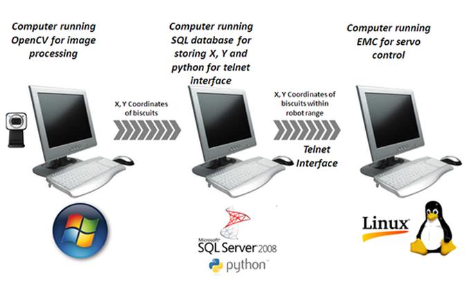
The entire system was interfaced in a peculiar manner. A computer running on Windows was dedicated to capturing images and run OpenCV for image processing. Image processing takes up significant memory space thus an entire RAM was reserved for it. The coordinates captured by OpenCV were passed to a second computer running SQL server and stored in the database. This computer was running an infinite while loop which would fetch the coordinates in the database as soon as they are within the reach of the robot and pass these coordinates to the third computer running the EMC software. There was a need for a third computer because the servo controlling software, EMC, was supported by linux where as SQL was supported by Windows. Python scripts were used to send coordinates from the windows based computer to the linux based computer via telnet. The figure below illustrates the process for ease of understanding.
Return to Top