Overview
The project was initially broken down into three major components: shelf traversal, book manipulation, and book identifications. For each component, three design alternatives were compared based on the given set of criteria. It was determined that a shelf mounted robot with a manipulator which pinches books and identifies them by reading barcodes was the optimal solution.
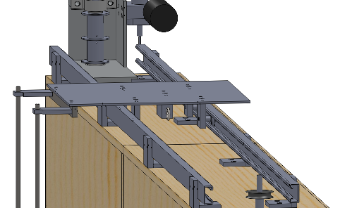
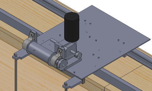
To achieve horizontal and vertical translation, a cabled pulley system was designed. For horizontal motion, a platform is mounted to the top of the shelf and is pulled on rollers along tracks by steel cables. The platform provides a mounting location for the main system electronics as well as for the vertical pulley system. The manipulator is driven vertically by a winch system which raises and lowers it along a set of vertical rails.
The robot will have a hash map of expected book positions which it will use to travel to its desired location on the shelf. A particle filter will be used to estimate the robot’s current position on the shelf and a linear quadratic regulator will be used to control it.
The manipulator utilizes lead screws to provide two degrees of freedom required to interact with books on the shelf. The manipulator features two pinch plates which can be extended and squeezed together to grab books. A unique design allows the manipulator to deal with most situations which can be encountered when retrieving and removing books.
The system will use dual monocular vision to identify books by reading barcodes and then will identify the edge of the desired book and align the manipulator with it. IR reflectance sensors will be used to maintain accurate vertical position of the manipulator relative to the shelf.
The system will contain an onboard embedded computer to perform real-time calculations. The computer will be wirelessly interfaced to a laptop from which the user can provide input.
Allowing for human operation within the operating environment of the robot is a key aspect of the design. The robot uses a LIDAR sensor to identify when a user is approaching the robot and enters an appropriate safe state depending on the proximity of the obstacle. The entire moving component of the robot will also be enclosed to keep humans from interacting directly with moving parts.
Constraints and Criteria
Based on the needs analysis performed the following set of design constraints was developed:
- The design must be compatible with existing library infrastructure.
- The design must be safe for human interaction.
- The design must not damage books.
- The design must not damage shelves.
- The design must correctly identify individual books.
- The design must safely retrieve books.
- The design must safely return books.
- The design must safely transport books.
A design which satisfies the full set of design constraints outlined above will be considered to have successfully met the needs of the problem area. In addition to the set of constraints which were identified, a set of design criteria were also developed for the purposes of evaluating possible solutions to the problem. The criteria are outlined below.
- Safety: The solution minimizes opportunities for human injury or interference.
- Complexity: A measure of the engineering design difficulty involved in the design.
- Cost: The dollar value of the components of the solution.
- Reliability: The design has a high chance of success in both retrieving and returning books.
- Installation: The design minimizes the cost and effort required to deploy the solution.
- Speed: A measure of the time saved versus a human worker performing the same or a similar task.
Traversal Design
It is required that the traversal system be able to position the manipulator accurately anywhere on the shelf where a book could potentially be. In order to provide this functionality, independent drive systems were designed for traversal in the horizontal and vertical directions. This section describes the detailed design process for each and how they operate together in the overall system.
Horizontal Traversal
It was required that a method for generating linear motion be selected. A rack and pinion mechanism, lead screw, driven roller, and cabled solution were all considered as design alternatives. In making the selection, four main factors were considered: positioning accuracy, generated force, cost, and ease of implementation. It was determined that a rack and pinion did not provide the required accuracy, a lead screw was expensive and difficult to implement over such a large span, and driven rollers were prone to slippage when put under load. A cabled system, on the other hand, excelled in all four areas and therefore was chosen as the drive method for the horizontal assembly.
Vertical Traversal
A driven pulley will be mounted to the horizontal traversing platform at the top of the shelf and act as a winch to raise and lower the manipulator along the vertical rails.
Manipulator Design
The developed design is based off of the Pinch and Extract method. The book manipulator design is centered around two vertical pinch plates that are used to grab books off of the shelf. The pinch plates are thin, rigid sheets of metal that can slide in betwe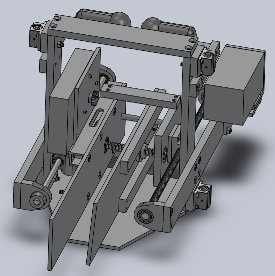 en the books on the shelf. The right plate is fixed to the manipulator while the left plate slides left to right to pinch the books between the plates. The two plates move into and out of the shelf on a rail and a lead screw. Two cameras are mounted on the top of the manipulator and they are used to track the location of each plate as well as scan the books on the shelf. There is a plate attached to the bottom of the manipulator for the book to rest on when it is brought on board for transfer.
Electrical
The core electrical system of the design is responsible for routing power to the various sub-systems and implementing the physical layer of all communications links. The core electrical system ties together the various processors, sensors, and actuators that allow the system to function. A block diagram illustrating the high level design of the core electrical system is shown below.
Power Distribution
As previously discussed the core electrical system is also responsible for routing power to all the sub-systems on the robot. The system’s power tree is presented below.
Embedded Control
The embedded control sub-system encompasses the MCU, as well as all of the sensors and actuators it interfaces to. A block diagram outlining the architecture of this component of the system is outlined below.
A PID controller will be implemented for each motor, allowing closed loop control of motor position based on feedback from a shaft mounted encoder. The gains of the controller will be tuned experimentally for optimal performance once the motor system is physically implemented.
Sensors
| Sensor | Function | Selection |
|---|---|---|
| LIDAR | User detection and safety | Hokoyu URG-04LX-UG01 |
| Camara | Book search & manipulator positioning | Logitech Quickcam Pro 9000 |
| Encoder | Position & velocity feedback | Grayhill 63R128 |
| Shelf Detector | Manipulator shelf alignment | Custom IR reflectance sensors |
Software
The control of the BRASS system will be performed using four main functional blocks. These blocks consist of the main controller, the traversal controller, the alignment controller, and the vision controller.
The main controller, seen in red, takes in the user input and sets the motor outputs based on the signals it receives from the other three controllers. The traversal controller uses the encoders and shelf sensors to create an estimate of the robots state and then to traverse the robot across the shelves to a desired set point. The shelf alignment controller is a simple closed loop controller that will align the robot with the current shelf. The vision controller is the most complex and is used to align the manipulator with the desired book location in order to perform removal and stocking operations.
Vision Controller
Once the traversal controller gets the robot to the approximate correct location on the shelving unit the vision controller takes over and searches the shelf for the target book. It does this by moving down the shelf at a constant speed checking each barcode against the target until the target is found. If the target is not found on the self the robot will switch back to the traversal controller and reset back to the beginning of the next shelf and continue searching. Once the target book is found within a frame the controller will move into the manipulator alignment mode.
The goal of the manipulator alignment controller is to align the two pinch plates of the manipulator with the edges of the target book such that the plates can be inserted to insert or remove the book. The purple ‘X’ marks the target barcode, the red line to the immediate left is the target edge, and the blue line is the manipulator position. The manipulator position relative to the image frame is a constant since both the camera and the plate are fixed to the same reference frame. Therefore the input distance, d, can be determined and fed to the alignment controller. The alignment controller is a simple PI controller which functions by attempting to drive the feedback signal, d, to zero. Once the distance d is zero the manipulator is aligned.
A PI controller should be sufficient to control the alignment process since the main objective is to ensure that there is zero steady state error. With a PI controller, by controlling the integrator constant, it should be possible to ensure this result. Once both controllers indicate that they are aligned the high level computer will signal to low level control unit to perform the removal or insertion operation.
Safety
Since the system is intended to function in the presence of patrons browsing the shelves manually it is important that the system includes safety features to handle these use cases. There are two main features that are included to ensure the safety of those around the robot. The first is a protective barrier which encapsulates the robot. This will be a plastic cylinder which will enclose the entire robot spanning from the floor to the top of the shelf. This barrier prevents patrons from being able to touch any moving parts which could harm them and it also prevents damage to the robot itself.
The second safety feature on the robot is a LIDAR sensor which is mounted at the bottom of the traversal mechanism. This LIDAR scans the aisle and determines if there are any obstructions which might interfere with the robot or that might endanger the user who might be browsing the books. Based on this distance to robot can determine if the object is close enough to be of concern. The aisle will be divided into three regions: the safe region, the slow region, and the stop region.
Safety is of the utmost importance to this project since any robot operating in a human occupied environment must ensure never to cause harm.