C
H
R
I
S
A
U
MECHATRONICS
ENGINEER
CHRIS AU
Welcome
PID, passivity, Kalman Filters, MPC and LQR. If this sprinkling of engineering terms causes no little gasp of excitement or quickening of the pulse, by all means congratulate yourself that you have not yet been sucked into the intricate world of control theory. For any true controls engineer, you see, the sight of the word “Kalman” will trigger a sudden private emotional response filled with anticipation.
As an engineer with a passion for control systems, I thrive on challenging projects that are multi-disciplinary in nature.
My hope is that this website makes it to those who are still in school, still deciding what career path to pursue, or those with a general interest in control theory and its many applications. I’ll try and showcase my coolest projects from grad school; most of which probably would have never seen the light of day again if it were not for this website. Maybe some of them will catch your eye and inspire you to pursue the same career path I have chosen.
Projects
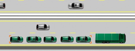
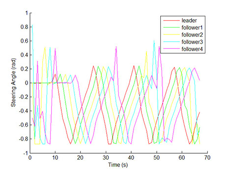
Model Predictive Controller for Vehicle Platoon CoordinationGrouping vehicles into tight platoons is very desirable because it reduces road congestion and also promises greater fuel economy, shorter commute times during peak hours and fewer traffic collisions. A model predictive controller (MPC) can be used for coordinating autonomous vehicle platoons. Essentially, information about the road trajectory and the position of the vehicle being followed are used to solve a constrained nonlinear optimization problem and plan the system behavior over a finite horizon. The solution to this problem was motivated by the fact that the MPCs can produce very near optimal solutions while also considering the system actuation restrictions like steering angle, steering rate, velocity and acceleration. The process of calculating the sub-optimal input is as follows:1) Measure/estimate the current system state2) Solve the optimization problem for the control action plan based on the horizon length3) Execute the first optimal control action in the action plan4) Repeat Note that while the control actions for T time steps in the future are solved, only the first control action is used before the optimization problem is solved again. This ensures that the problem remains stable and feasible after executing the first control action. The following video shows the tracking performance of a vehicle platoon for a square road trajectory using Matlab. Due to the abrupt changes in the desired trajectory and the length of the planning horizon, the system is not expected to track the road perfectly. However, it can be seen that the results are quite good. In the two remaining graphs, it can be seen that the vehicle velocities and steering inputs respect the acceleration and steering rate constraints that have been set. These constraints are necessary for the MPC to create realizable input commands that can be implemented on an actual system. 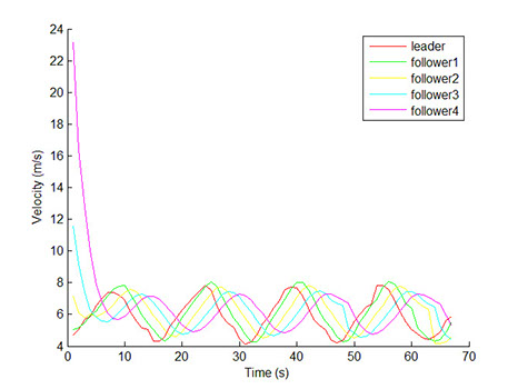
 More details can be found here: Model Predictive Control for Coordination of Vehicle PlatoonsSliding Mode Controller for Vehicle Torque VectoringWhen the driver turns the steering wheel in a vehicle, he/she expects the vehicle to change its direction. However, under certain conditions, the response of the vehicle may not meet the driver’s expectations due to vehicle understeering or oversteering.
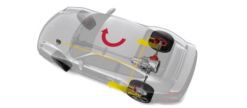
 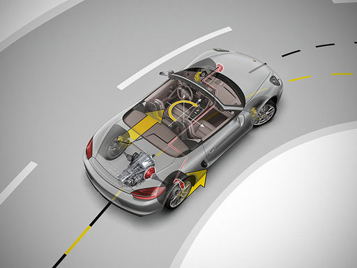 In the industry, a vehicle is usually tuned through a bump steer test; static settings are then applied to give it a stable response at different speeds. These conventional methods make the vehicle’s response dull. Torque vectoring (TV) is a method that reduces the tradeoff between vehicle stability and performance. In particular, the vehicle’s commanded yaw rate response can be improved by increasing the drive torque to the outside wheels while simultaneously reducing the torque to the inside wheels to create a moment force on the vehicle. Without getting too specific on the math, the vehicle’s steering angle commanded by the driver is converted to the desired vehicle yaw rate and side slip angle via a reference model. The designed controller must then calculate the required torque transfer between the left and right rear-wheels to generate a moment force on the vehicle so that the yaw rate error between the desired and actual approaches zero. Due to the uncertainties in the system, there needs to be some level of robustness in the controller design. A sliding mode controller fits this requirement very well because it is insensitive to parameter uncertainty, disturbance and noise thanks to the nonlinearity (discontinuous feedback) in the control law. The equilibrium can be shown to be globally asymptotically stable using a Lyapunov candidate function based on the smoothed error. The basic design of the sliding mode controller hinges on the concept of a sliding surface which is essentially a line that contains the desired state of the system and the system input. The goal of the controller is for the system state to reach the surface in finite time and stay on the surface as if it was an invariant set. When the control parameters are chosen correctly, the state trajectory will "bounce" back and forth on the line. The video on the left validates the improvement to the car’s steering response due to torque vectoring by plotting the car’s absolute position relative to the inertial frame. Clearly, the turning radius of the blue vehicle with TV is tighter than the red vehicle without TV. The following two graphs show a comparison between a state feedback controller and a sliding mode controller for a sinusoidal steering input. The one on the left shows the yaw rate tracking and the one on the right shows the corresponding torque transfer. When the controller is turned off, tire slip causes the vehicle to understeer, resulting in a smaller yaw rate than what the driver desires. Both controllers produce significantly better tracking results than without the TV controller. It can be seen that the sliding mode controller offers slightly better tracking dynamics than the state feedback controller with the controller parameters chosen. It can also be seen that the torque transfer input from the sliding mode controller is smoother than the input from state feedback. This is because of the robustness of the sliding mode controller to sensor noise. In the state feedback controller, noise is inherent in the control signal because it propagated through the feedback loop.
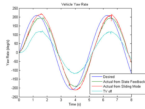
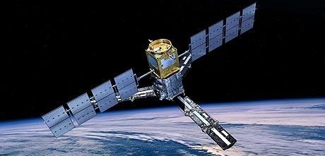
![]() More details can be found here: Torque Vectoring PresentationAcknowledgments: Moeed Siddiqui and Yujie Guo Robust Adaptive Tracking Controller for Spacecraft AttitudeThere are several ways to design a controller to track the attitude of a spacecraft. In general, controlling a spacecraft is inherently difficult because it is a MIMO nonlinear system. Also, parametric uncertainties in the system plant model and non-parametric uncertainties may lead to system performance degradation and/or instability. Based on these challenges, a robust adaptive tracking controller for a rigid spacecraft using Quaternions was designed and simulated using Simulink. The problem with a PD feedback and feedforward tracking controller is that the inertia matrix needs to be exactly known. However, on a real system, these parameters cannot be known with absolute certainty and may even be time varying. Thus, an adaptive component is desired for the controller to estimate the inertia and achieve a consistent performance in the presence of large load variations. With adaptation, the reference plant model parameters will change slowly over time and decrease the tracking errors of the controller. The control and adaptation law can be derived with Lyapunov stability and the equilibrium can be shown to be GAS by Lyapunov and Barbalat's lemma. Something very interesting to note about adaptive controllers is that the estimated inertia matrix parameters may not converge exactly to the actual values. This may sound counter intuitive, however, the objective of the controller, by design, is to generate values that allow the tracking errors to converge to zero. If convergence of the estimated parameters to the actual parameter values is desired, the trajectory must be sufficiently “rich” such that there is no other way to track the trajectory without the estimated parameters converging to the actual values. One benefit in using an adaptive controller for spacecraft attitude tracking is that it is robust to parametric uncertainties. On the other hand, non-parametric uncertainties can lead to performance degradation in the adaptive controller, and in the worst case, instability. Examples of nonparametric uncertainties include high frequency unmodelled dynamics, like actuator dynamics and structural vibrations, and low frequency dynamics, like friction, measurement noise and computational round-off error. In effect, non-parametric uncertainties will cause drifting of the estimated parameter values because the adaptation mechanism will have difficulty distinguishing between poorly estimated parameters and system noise. Eventually, it is quite possible that the parameters will drift to the point where the closed-loop poles enter the right hand plane. This is very dangerous since the adaptive control system can suddenly fail. To combat this, a mechanism is needed to prevent the adaptation of the system to portions of the signals that are not part of the plant dynamics. Similar to the concept of “over-training” in machine intelligence, the “over-adapting” by the controller is not desired. To do this, a sliding mode controller can be used to augment the adaptive controller based on a textbook called “Applied Nonlinear Control” by Slotine and Li to increase system robustness. Essentially, controller robustness is achieved by creating a dead zone where the system does not adapt once the smoothed errors reach steady state. Using a modified adaptation law and the same control law as the adaptive controller, it can be shown that the equilibrium is once again GAS using Lyapunov and Barbalat’s lemma.
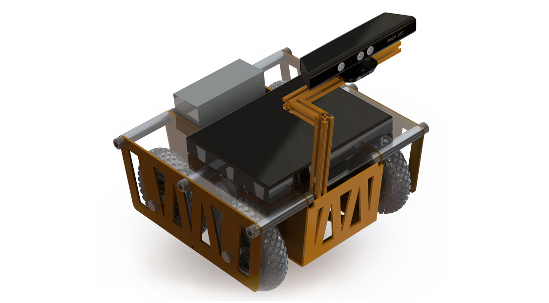
More details can be found here: Torque Vectoring PresentationAcknowledgments: Moeed Siddiqui and Yujie Guo Robust Adaptive Tracking Controller for Spacecraft AttitudeThere are several ways to design a controller to track the attitude of a spacecraft. In general, controlling a spacecraft is inherently difficult because it is a MIMO nonlinear system. Also, parametric uncertainties in the system plant model and non-parametric uncertainties may lead to system performance degradation and/or instability. Based on these challenges, a robust adaptive tracking controller for a rigid spacecraft using Quaternions was designed and simulated using Simulink. The problem with a PD feedback and feedforward tracking controller is that the inertia matrix needs to be exactly known. However, on a real system, these parameters cannot be known with absolute certainty and may even be time varying. Thus, an adaptive component is desired for the controller to estimate the inertia and achieve a consistent performance in the presence of large load variations. With adaptation, the reference plant model parameters will change slowly over time and decrease the tracking errors of the controller. The control and adaptation law can be derived with Lyapunov stability and the equilibrium can be shown to be GAS by Lyapunov and Barbalat's lemma. Something very interesting to note about adaptive controllers is that the estimated inertia matrix parameters may not converge exactly to the actual values. This may sound counter intuitive, however, the objective of the controller, by design, is to generate values that allow the tracking errors to converge to zero. If convergence of the estimated parameters to the actual parameter values is desired, the trajectory must be sufficiently “rich” such that there is no other way to track the trajectory without the estimated parameters converging to the actual values. One benefit in using an adaptive controller for spacecraft attitude tracking is that it is robust to parametric uncertainties. On the other hand, non-parametric uncertainties can lead to performance degradation in the adaptive controller, and in the worst case, instability. Examples of nonparametric uncertainties include high frequency unmodelled dynamics, like actuator dynamics and structural vibrations, and low frequency dynamics, like friction, measurement noise and computational round-off error. In effect, non-parametric uncertainties will cause drifting of the estimated parameter values because the adaptation mechanism will have difficulty distinguishing between poorly estimated parameters and system noise. Eventually, it is quite possible that the parameters will drift to the point where the closed-loop poles enter the right hand plane. This is very dangerous since the adaptive control system can suddenly fail. To combat this, a mechanism is needed to prevent the adaptation of the system to portions of the signals that are not part of the plant dynamics. Similar to the concept of “over-training” in machine intelligence, the “over-adapting” by the controller is not desired. To do this, a sliding mode controller can be used to augment the adaptive controller based on a textbook called “Applied Nonlinear Control” by Slotine and Li to increase system robustness. Essentially, controller robustness is achieved by creating a dead zone where the system does not adapt once the smoothed errors reach steady state. Using a modified adaptation law and the same control law as the adaptive controller, it can be shown that the equilibrium is once again GAS using Lyapunov and Barbalat’s lemma. ![]() In the simulation, the spacecraft will attempt to track an arbitrary trajectory defined by a sinusoid in the yaw direction for 37 seconds, then ramp up and down in yaw, roll and pitch for 20 seconds and finally go back to the spacecraft’s initial state and maintain that constant attitude. The figure on the left show the tracking result for the final controller design using PD feedback, feedforward, sliding-mode and adaptive components. Notice how the tracking of the desired trajectory is almost exact with almost no tracking delay. More details can be found here: Spacecraft Attitude Robust Adaptive ControlSLAM and Sound Source Localization for Search and RescueSearch and rescue is physically arduous, mentally demanding, and dangerous for first responders. Upon entering a disaster area, rescue personnel often have little to no knowledge of the actual state of the building, and only educated guesswork to go on for locating victims. As a result, the use of robots to assist in rescue operations is very desirable. As part of my 4th year engineering design project, a semi-autonomous robot was created to collect information about the environment. In particular, the remote operated robot uses simultaneous localization and mapping (SLAM) to create a 3D map of its surroundings in real time using the depth map data returned from a Kinect sensor. Once collected, the compressed data is sent wirelessly by the onboard computer running ROS to a more capable desktop computer to process the data and create the mesh using Kinfu Large Scale. This 3D maps gives rescuers a better understanding of the situation they are entering before they put themselves at risk. The robot also utilizes the microphone array on the Kinect sensor to perform sound source localization using HARK. Essentially, by searching for a specific frequency band of sound that most closely corresponds to the human voice, the robot is able to determine the approximate direction of survivors in a disaster area. This also allows the robot to explore areas that are outside the robot’s visual range by listening beyond doors and physical obstructions. Kinect SensorVideo stream, depth info, sound data
In the simulation, the spacecraft will attempt to track an arbitrary trajectory defined by a sinusoid in the yaw direction for 37 seconds, then ramp up and down in yaw, roll and pitch for 20 seconds and finally go back to the spacecraft’s initial state and maintain that constant attitude. The figure on the left show the tracking result for the final controller design using PD feedback, feedforward, sliding-mode and adaptive components. Notice how the tracking of the desired trajectory is almost exact with almost no tracking delay. More details can be found here: Spacecraft Attitude Robust Adaptive ControlSLAM and Sound Source Localization for Search and RescueSearch and rescue is physically arduous, mentally demanding, and dangerous for first responders. Upon entering a disaster area, rescue personnel often have little to no knowledge of the actual state of the building, and only educated guesswork to go on for locating victims. As a result, the use of robots to assist in rescue operations is very desirable. As part of my 4th year engineering design project, a semi-autonomous robot was created to collect information about the environment. In particular, the remote operated robot uses simultaneous localization and mapping (SLAM) to create a 3D map of its surroundings in real time using the depth map data returned from a Kinect sensor. Once collected, the compressed data is sent wirelessly by the onboard computer running ROS to a more capable desktop computer to process the data and create the mesh using Kinfu Large Scale. This 3D maps gives rescuers a better understanding of the situation they are entering before they put themselves at risk. The robot also utilizes the microphone array on the Kinect sensor to perform sound source localization using HARK. Essentially, by searching for a specific frequency band of sound that most closely corresponds to the human voice, the robot is able to determine the approximate direction of survivors in a disaster area. This also allows the robot to explore areas that are outside the robot’s visual range by listening beyond doors and physical obstructions. Kinect SensorVideo stream, depth info, sound data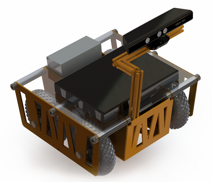 4x DC Motors337 watts eachArduino Micro-controllerCommunication interface between laptop, motor controllers and encodersLead Acid Battery17 Ah capacitySlave ComputerSends/receives ROS messages
 Acknowledgments: John Van Oort, Muny Tram and Derek ChowMPC for Vehicle Platoon CoordinationSliding Mode Controller for Vehicle Torque VectoringAdaptive Tracking Controller for Spacecraft AttitudeSLAM and Sound Source Localization for Search and Rescue
![]()

 4 - 4<>About Me
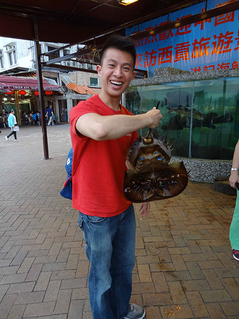
Chris is a Mechatronics Engineering graduate from the University of Waterloo and a Systems Control Engineering graduate from the University of Toronto. He has had the fortunate opportunity to work in several different industries as a co-op student including smartphones, steel making, nuclear energy, manufacturing automation, grid-scale energy storage and, most recently, in vehicle stability and braking systems.
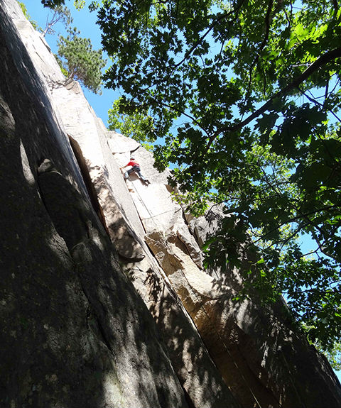
Outside of school and work, he enjoys staying active, exploring the great outdoors and constantly learning new things (especially if it’s related to controls).
Contact Information
Please feel free to contact me if you have any questions or if you would like to suggest improvements to this website.
![]()
© Copyright 2014 | Chris Au