Design overview
There are three critical elements to the design of the team's intended UAV navigation system:
- Feature Recognition / Obstacle Avoidance
- Localization
- Altitude Control
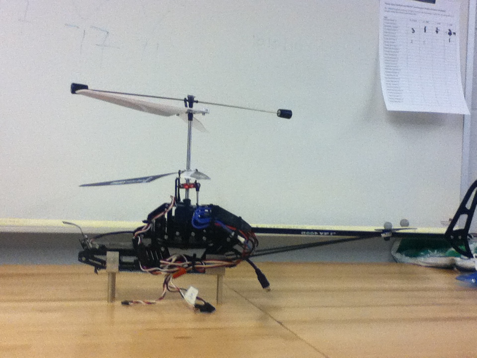
Figure 1. This is a picture of the UAV which the
team is currently working on
Sensor selection
1. Webcam for feature recognition and localization
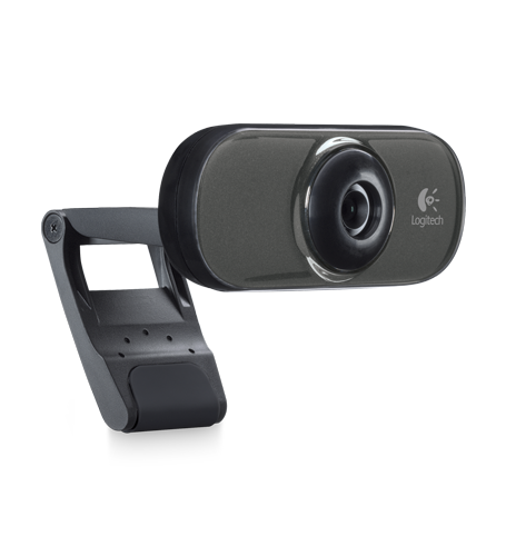
Figure 2. Logitech Webcam C210
(picture from http://www.logitech.com/en-ca/notebook-products/webcams/devices/7022)
A conventional Logitech Webcam C210 will be mounted at the front of the UAV and will be responsible for taking images of the surrounding environment. After the images that are taken from the webcam are properly processed, the UAV will be able to recognize specific geographic features (e.g. coloured window) and able to identify its location relative to the identified feature (localization).
2. Sonar sensor for altitude control
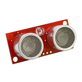
Figure 3. Sonar Rangefinder SRF08
(Picture from http://www.acroname.com/robotics/parts/R145-SRF08.html)
A sonar sensor SRF08 will be mounted at the bottom of the UAV for the sole purpose of tracking its altitude. The specification for the sonar sensor is summarized below:
| Specifications | |
|---|---|
| Voltage | 5 V |
| Current | 15 mA Typ. 3 mA Standby |
| Frequency | 40 kHz |
| Minimum Range | 3 cm |
| Maximum Range | 6 m |
| Max Analogue Gain | Variable to 1025 in 32 steps |
| Connection Type | I2C |
| Light Sensor | Front facing light sensor |
| Timing | Fully timed echo, freeing host computer of task |
| Echo | Multiple echo - keeps looking after first echo |
| Units | Range reported in µS, mm or inches |
| Weight | 11.3 g (0.40 oz) |
| Size | 43 x 20 x 17 mm (1.69 x 0.78 x 0.67 in) |
(Retrieved from http://www.acroname.com/robotics/parts/R145-SRF08.html)
Mechanical frame design
A new mechanical frame had to be designed to mount the two sensors (sonar sensor and a webcam) onto the UAV. A new mechanical frame design is outlined as below:
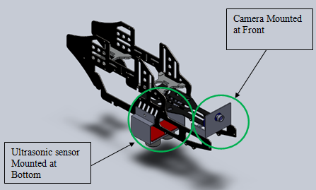
Figure 4. Mechanical Frame Design of The UAV
software & algorithm design
1. Feature RecognitionAs for the feature recognition, it was decided that the UAV must be able to distinguish a blue coloured window frame from other surroundings, while identifying the four corner points of the window.
This feature recognition could be achieved by implementing a series of image filters as listed.
- Colour filter identifies a blue-coloured objects
- Canny edge detection detects the edges in the image
- Houghline transform comes up with four straight lines which represents the window frame based on its voting mechanism
- Harrris corner detection method was used to identify the four corner points of the window.
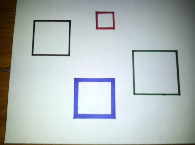
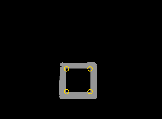
Figure 5. Image on left shows the original image taken from the webcam, while the right side image represents the filtered image after above three filters are applied. In this image, the system was successfully able to identify the blue-coloured frame with its four corners.
2. Localization
To identify the UAV's location relative to the recognized feature (blue-colour window frame), a 4 by 4 camera matrix will be applied to the image taken.
Based on the know focal length of the webcam and the known dimention of the window, and with the application of the camera matrix, it is possible to figure out pitch, yaw, roll angle of the webcam and its distance relative to the window, which can be used to figure out the relative location of the UAV in repect to the window.
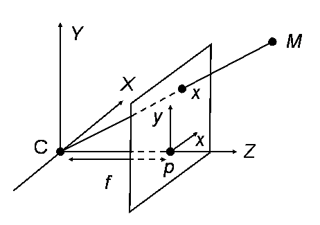
Figure 6. Simple diagram showing how camera matrix works
3. Altitude Control
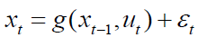
During its operation, we would like to keep the UAV to be flying at constant altitude in a stable manner. To do this, an extended kalman filter will be used.
An extended kalman filter accounts for nonlinearities in the motion and measurement model. Thus, this filter is suitable for uses in non-linear system such as in altitude control application for the UAV, which is expected to be non-linear and quite volatile.
The model summary for extended kalman fileter is shown below.
Motion Model:
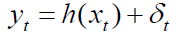
Measurement Model:
Linearization:
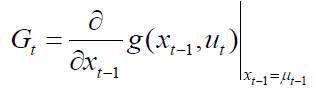
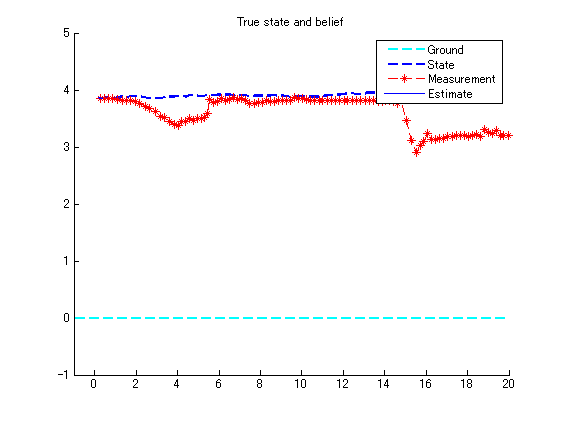
Figure 7. Simulation result from the application of extended kalman filter
Hardware/software interface design
The above elements that are discussed are organized into the overall hardware/software diagram as shown below:
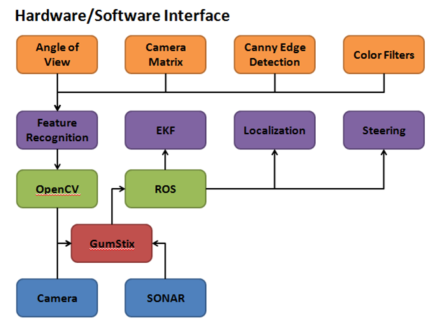
Figure 8. Hardware/Sofware Interface Diagram
The bottom level corresponds to sensors that feed in new
data to the
vehicle for state estimation. Gucstix and MCU does the algorithm and
system
calculation. OpenCV and ROS is open
project code that is read through to determine the appropriate
functionality.