 |
 |
MRR - Electrical Design
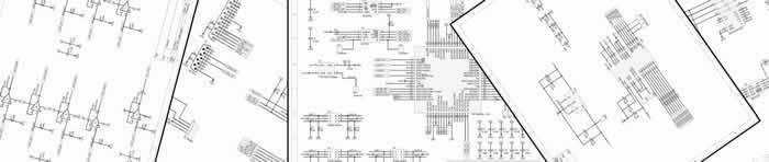
 The electrical and communications architecture of the MRR is based on decentralized control scheme where each joint is controlled independently. A Controller Area Network (CAN) communication bus synchronizes the operation of all the joint and connects a host computer to all the nodes. To decrease the weight of the joints, the power amplifiers and drives are positioned at the base of the manipulator. The drives supply the electrical power to the motors, while receiving the command signals from the controller nodes.
In LAIR and LCIA lab and with the feedbacks of Sterner Automation engineers and management, I designed the electrical architecture and validated the compatibility of the electro-mechanical interfaces in the electrical level. I was also engaged in the selection of suitable electrical motors, motor drives, and force/torque sensor.
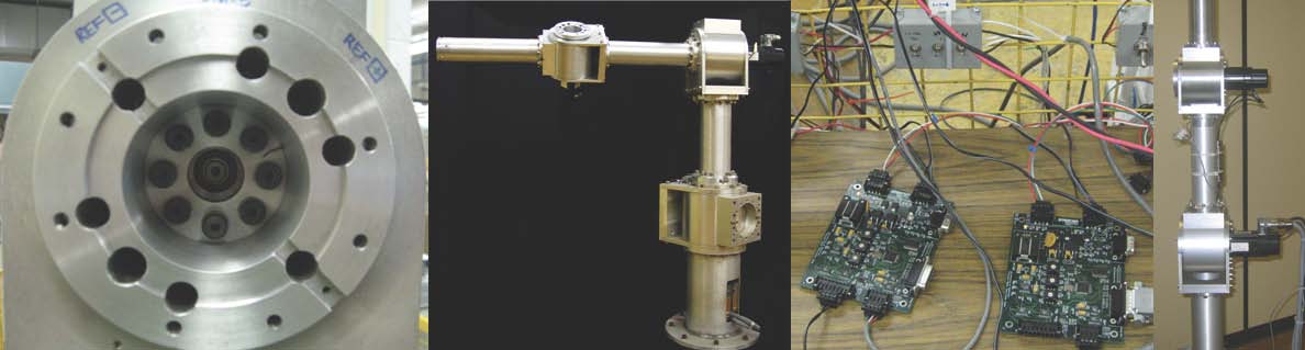
 The controller nodes (MCU boards) were designed and implemented specifically for this project. Each control node consists of a Microcontroller, power regulation, ADC, DAC, on board RAM extension, Serial interface, CAN interface, surge protection, and SPI units.
Using the expertise and know-how of Sterner Automation I designed the controller nodes, including all the steps of circuit design, part selection, simulation, and PCB design.
I supervised four grad-students in developing the low-level code for the controller nodes. I developed the high-level control and communications firmware myself. The embedded code was developed using HI-TECH PICC-18 compiler.
[video]