
The most important parameter governing electroosmotic flow is the zeta potential which is the electrostatic potential at the shear plane in the electric double layer. Because the zeta potential is influenced by many factors it is largely unique and must be measured experimentally for each solid/liquid interface. However, the zeta potential cannot be measured directly, instead its value is usually inferred from electroosmotic velocity measurements. If the electroosmotic velocity is known then the zeta potential can be calculated from the following equation:
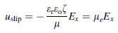
where uslip is the electroosmotic velocity, Ex is the electrical field, εr is the fluids dielectric constant, εo is the vacuum permittivity, µ is the viscosity of the fluid, ζ is the zeta potential , and µe is a proportionality factor known as the electroosmotic mobility.
A common technique used to measure the zeta potential is the current monitoring method where the electroosmotic velocity is detemined by monitoring the change in electric current that occurs when the test solution is displaced by a similar solution of slightly different concentrattion (and conductivity) inside a microchannel. If the concentration difference is kept small (<5%) the current change is linear (see figure below). The electroosmotic velocity can be calculated by knowing the time it takes for the displacement and the length of the channel or from the slope of the trend.
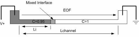
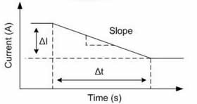 Schematic representation of the current monitoring technique (Left) and the current-time plot obtained during an experiment (Right).
The major problem associated with the single channel method is the ambiguity surrounding the displacement time. Current fluctuations and gradual transitions due to diffusive mixing at the liquid/liquid interface makes pinpointing the exact beginning and end of the displacement process difficult. The process is also time consuming since the solutions in the reservoirs must be replaced manually each time a displacement is performed. To solve these issues, a new Y-channel design was proposed that would allow for more accurate measurements and higher throughput.
The design consists of two side channels attached to the main displacement channel as shown in the figure below. The 100% and 95% solutions are placed in the two branch reservoirs and an alternating electric field pumps the solutions down the displacement channel. In this way multiple displacements can be obtained quickly without having to refill the reservoirs. In addition, the design creates a well defined interface so that the start and stop times can easily be determined as shown in the current-time plot below.
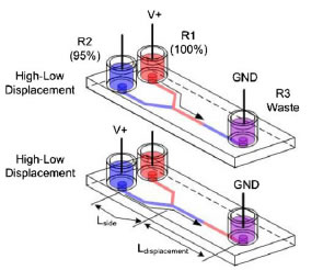
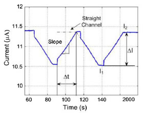 Schematic representation of the Y channel current monitoring method(Left) and the current-time plot obtained during an actual experiment for 1XTBE with annotations (Right).
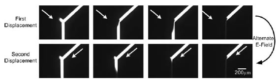
A number of issues that influence the accuracy of the zeta potential measurments were also addressed in the design of the Y-channel. These issues include minimizing the current draw in order to suppress joule heating and electrolysis which can cause unwanted changes in the conductivity and pH of the test solution. Also, reducing undesired pressure driven flow caused by small differences in liquid levels and meniscus shapes which can lead to additional fluid flow. The figure below shows the switching process for two sequential displacements using a flourecent dye for visualizaton.
The new Y-channel design was applied to measure the zeta potential of a number of solutions in PDMS/PDMS and PDMS/Glass microchannels. Each measurement represents the average result obtained from over 80 displacements, nearly 20 times the amount usually reported in literature.
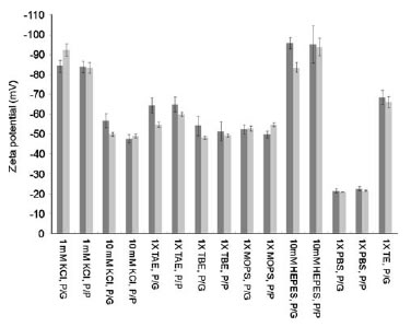
Plot of the zeta potential for various solutions using the total length (light) and slope method (dark).
For more information on this project please refer to the following publication:

University of Waterloo
200 University Avenue West
Waterloo, Ontario, Canada N2L 3G1
519 888 4567
contact us | give us feedback | http://www.uwaterloo.ca